Most LEDs are simple single device with two leads but packages with two or more LEDs are common and there are various LED pinouts in use.
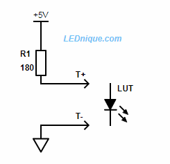
Simple LED test circuit
Simple LED test circuit. ‘LUT’ stands for ‘LED under test’!
Most LEDs will light at less than 5 V and can tolerate 5 V reverse voltage. A 5 V supply is available from a USB supply or, for example, an Arduino. You can use a higher voltage such as a 9 V battery and double the value of R1 but you might damage sensitive devices on reverse voltage.
See Testing unknown LEDs for more on this topic.
Note that LEDs usually have no two pins the same length. This is for two reasons:
It helps identify the pins.
It helps during assembly as pins can be inserted one at a time from longest to shortest without having to align all the pins simultaneously.
2-pin
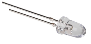
The most common type of LED is the 2-pin, 5 mm, round lens type. Generally these are a single LED. Polarity is indicated by the long lead (+ / anode) or the flat on one side of the base (- / cathode).
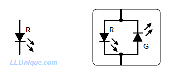
A typical 2-pin LED.The two-pin package can contain a single or two back-to back LEDs.
Be aware that bi-colour LEDs are also sold in this package. Some are dual-colour so that reversing the current through them changes the colour. Others may have both LEDs the same colour and this can be useful in AC applications as it can conduct on both cycles of the mains and eliminates the need for a rectifier.
The bi-colour LED’s datasheet will specify which way round to connect to ensure the correct colour.
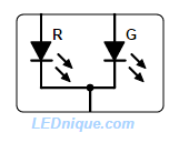
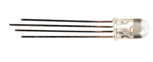
3-pin
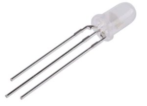
A 3-pin LED.
The three-pin LED is usually a pair of LEDs of different colours sharing a common anode or common cathode. Either LED can be turned on independently or blended to create a combination.
A bi-colour, 3-pin, common-cathode LED.
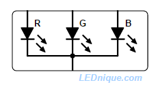
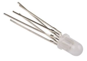
4-pin
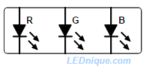
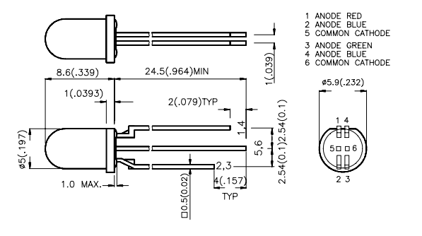
The popular RGB, 4-pin, LED allows generation of colours across the visible spectrum.
The 4-pin package is most commonly seen on RGB (red-greeen-blue) LEDs. Common cathode and common anode versions are available.
An RGB LED in a 4-pin package. Note that this one has a common cathode.
6-pin
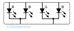
RGB with individual pinouts allows common anode, common cathode configuration as well as series connection of the LEDs.
When the number of pins reaches six all sorts of strange variations are possible. One sensible one is to bring out each LED anode and cathode on individual pins. This allows a single part to be used for common anode, common cathode and series LED configurations.
A slightly strange 6-pin, RB-GB, LED, has two separate 3-pin LEDs in one package.
This package consists of a red-blue pair and a green-blue pair in one package. Note two, independent common cathodes.Kingbright LF5WAEMBGMBW, 6-pin, RB-GB LED has two 3-pin LEDs in one package. Both have a blue LED. Note the pin length orientation clue.
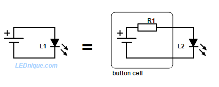
Figure 1. Many cheap tiny LED lamps use button cells (or battery) and an LED with no sign of current limiting resistor. But there is one – the battery internal resistance.A typical key-fob lamp has a button cell or battery (visible through the case) a push-to-make switch and an LED.
The fact that many of the cheap key-fob lights use a button cell and LED with no sign of a series resistor or any current limiting often causes some confusion. If the LED doesn’t burn out in this case when connected to a 3 V battery then what’s all the fuss about current limiting and series resistors?
The answer is that there is a series resistor; we just can’t see it! All cells and batteries have some internal resistance. We usually model batteries as an ideal, constant voltage source with a series resistance.
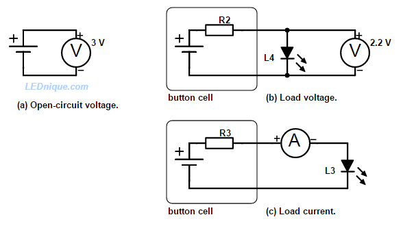
Figure 2. Measuring the no-load cell voltage and the loaded cell voltage allows us to measure the internal cell resistance.
In Figure 2a we measure the open-circuit voltage of the battery and read 3 V.
In Figure 2b we measure the voltage again with the LED connected. We find that it is 2.2 V.
(c) We switch the meter to mA and connect it in series with the LED. We measure 30 mA.
With these three measurements we can calculate the internal resistance of the cell. The voltage drop is 3 – 2.2 = 0.8 V at 30 mA so, using Ohm’s law we can calculate the internal resistance as
Note that the internal resistance may not be constant as it is due to complex chemical and physical action within the cell. If you repeat the measurements with two LEDs in parallel you will get another but close value. If you short out the cell with your ammeter you will get a different value again and usually higher as you are pulling much higher current.
The lesson?
Just because it works with a button cell, it doesn’t mean it’s a good idea with other power sources. Repeating the test with a battery of lower internal resistance will raise the current and may destroy the LED. Placing the LED across a regulated 3 V supply will definitely blow the LED. See the IV curves page for more details.
Other reading
To calculate the power dissipated in the internal resistance see the power calculation article.
LEDs are replacing incandescent light bulbs in many applications and over the next decade or so we are likely to see very few bulbs in new products. There will always be special cases where certain features of the light bulb make it the best choice – e.g., broad continuous spectrum or both light and heat are required.
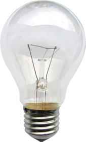
Incandescent light bulb
Incandescent light bulb with tungsten filament.
LEDs differ from light bulbs in many respects.
Light bulbs are resistors designed to glow white-hot when connected to the rated voltage. They can heat up to 2,500°C.
They behave like resistors. But like most metallic resistors the resistance increases with temperature. (This means that the temperature coefficient of resistance is positive – a PTC.)
When cold the resistance is much lower than running temperature so the initial surge current can be 15 times that of the steady state current. For example, a 100-watt, 120-volt lamp has a resistance of 144 Ω when lit, but the cold resistance is much lower (about 9.5 Ω). This is why incandescent bulbs are prone to blow on switch-on. A weakened filament will burn
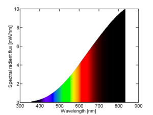
Spectral power distribution of a 25 W incandescent light bulb.
out with the high inrush current.
They can be run on DC or AC.
Bulbs are tolerant of voltage variation of ±10% which is normal on mains supplies.
Bulbs can be made to run directly on a wide range of voltages such as 3 V bicycle lamps to mains voltage lamps of several hundred volts.
Bulbs emit light over a broad spectrum from infra-red through the visible spectrum but heavily weighted to the red end. This is most noticeable in film photos which exhibited a characteristic tungsten red cast. The broad spectrum should not be confused with mixing specific colours or wavelengths to fool the eye into seeing white light.
Bulbs are fragile.
LEDs
LEDs are different in nearly every regard.
LEDs drop in apparent resistance with rising voltage. This is due to the diode’s IV curve. See IV curves.
LEDs have a slight negative temperature coefficient (NTC) value. This means that as they warm up they will pass more current and tend to heat further. If not managed this will lead to over-current failure. See LEDs in parallel – the problem.
LEDs are low voltage. Typical LED forward voltages are 1.2 V (infra-red) to 5 V (white).
LEDs cannot handle negative voltages and require a DC supply. Most LEDs are rated for maximum 5 V reverse voltage.
LEDs are sensitive to electro-static discharge (ESD). (Bulbs are not.)
LEDs’ colour is a function of the semiconductor material and are available in colours from infra-red to ultra-violet. See RGB LED.
LEDs can detect light with a small output current like photodiodes.
LEDs are single sided even with a transparent substrate.
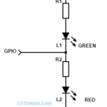
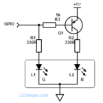
1 GPIO, 2 LEDs A single GPIO pin can be used to light two LEDs. How it works When the output is switched low current will flow from the positive supply via R1 and the L1, green, to the output pin. L1 will illuminate. L2, red, will be shorted out and will be dark. When the … Continue reading "One switch or GPIO / multiple LEDs"
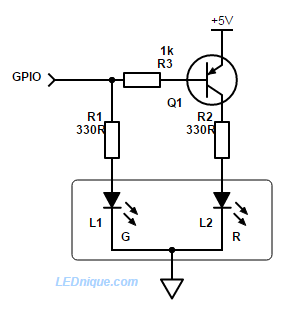
Driving a bi-colour LED with one pin is possible! When GPIO pins are in short supply a dual red-green common-cathode LED can still be used with the addition of a PNP transistor and base resistor. How it works When the GPIO pin is high L1, green, is turned on. There is no bias current for … Continue reading "1 GPIO, bi-colour LED, common cathode"
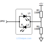
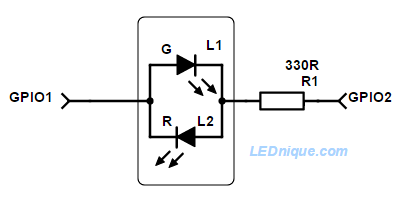
Driving a bi-colour, 2-pin LED with one pin is possible! When GPIO pins are in short supply a bi-colour 2-pin LED may seem like a good idea. It can be done, but is not that efficient. How it works When GPIO is low R1 provides current to L2 and the indicator glows red. When GPIO is … Continue reading "1 GPIO, bi-colour, 2-pin LED"
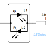
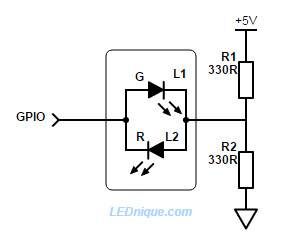
If two GPIO pins are available controlling a 2-pin bi-colour back-to-back LED is simple. How it works To light L1, green, switch GPIO1 high and GPIO2 low. Current will flow from left to right. To light L2, red, switch CPIO2 high and GPIO1 low. Current will flow from right to left. To cross-fade or mix colours toggle between … Continue reading "2 GPIO, 1 bi-colour 2-pin LED"
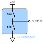
Most micro-controllers and logic families have output stages which can connect the output to the positive supply or to ground. This allows the micro to put a definite ‘high’ (+5 V in this example) onto the output or a definite ‘low’ (ground) rather than let it float which could cause problems if the output is feeding … Continue reading "High-side versus low-side switching"
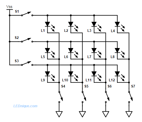
Multiplexing is a technique used to connect devices – typically LEDs (for displays) or buttons (for keyboards) – in a matrix of addressable rows and columns. The advantage is simplification of hardware due to the reduced number of pins required. Multiplexed displays using seven-segment LEDs remain popular due to low cost and high brightness.
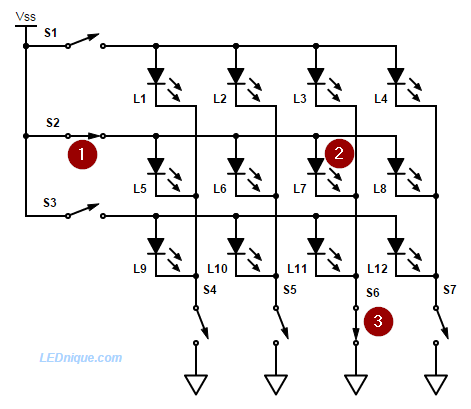
Figure 1. An LED matrix display. Each LED can be turned on individually by closing the appropriate row and column switches. In practice some form of current limiting is required.Figure 2. By closing switches 2 and 6 we can turn on LED 7 alone. Current flows through (1), (2) and (3).
A practical circuit uses tranistorised switches. Each row is switched on in sequence (S1, then S2 and then S3) and the corresponding switches S4, 5, 6 and 7 closed in synch to switch on the desired LEDs. To fool the eye into seeing a continuous display the sequencing is typically done at more than 50 times per second.
In the example of Figure 1, only seven lines are required to switch twelve LEDs. The pin-count saving increases with larger displays as the pin-count (for a square matrix) is the square root of the number of LEDs. This reduces the pins required on the controller, reducing cost and circuit board complexity.
Since the LEDs are now on for only a fraction of the time it is necessary to pulse them with higher current. See LED current rating for more details.
Sneak paths
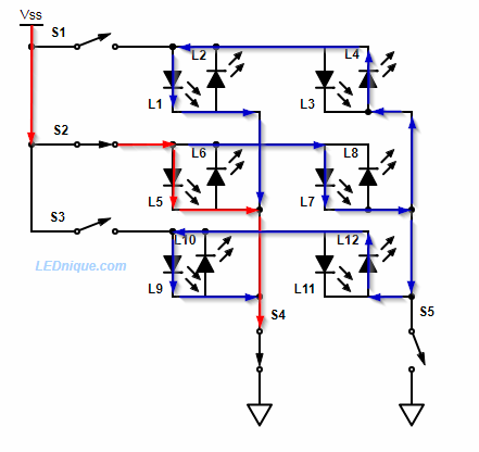
Figure 3. If reverse currents are possible through the LEDs then unexpected problems can result.
Figure 3 shows a problem that can occur on higher voltage supplies if reverse current flow is possible. (This can happen on keyboard matrices if diodes are not used to prevent it.) In this case we might expect that with S2 and S4 closed that only L5 will light. There are, however, sneak paths as shown in blue on the diagram and ghosting may appear on other LEDs. With non bi-directional LEDs this will not be a problem.
Alphanumeric multiplexed display
A six-character sixteen-segment alpha-numeric display and two-digit seven-segment multiplexed LED display on a DigiTech RP335 guitar effects unit. Exposure time 1/15 s.A 1/2000 s photo of the same display catches the alpha character ‘N’ lit up on one of the sixteen-segment displays.Another 1/2000 s shot of the same display catches the two seven-segment numeric displays lit simultaneously.
The fact that the two 7-segment displays are on simultaneously suggests that these displays are wired in seven “columns” (six for the alpha displays and one for the pair of digits) and sixteen “rows” (one per starburst segment). The alpha characters require sixteen data lines so it makes sense to connect the two seven-segment displays to fourteen of these and strobe them all at once.
This video demonstrates the multiplexing display using a video camera under varying background illumination.
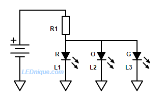
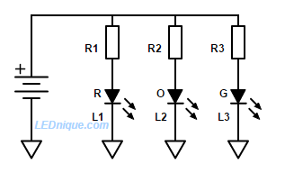
Many beginners ask why LEDs can’t be wired in parallel to share a common current-limiting resistor as shown in Figure 1. Well they can – but it’s usually not a good idea to parallel LEDs directly.
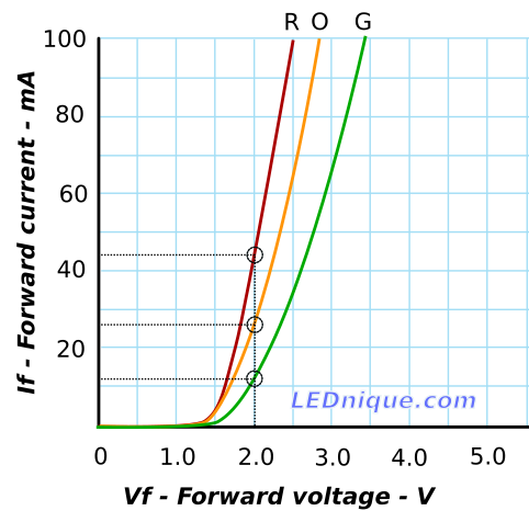
Figure 2. IV curves for red, orange and green in parallel and current through each one.
In this example we’ll first consider the case of parallel connection of a red, orange and green LED. If the value of R1 chosen in Figure 1 were to result in a common voltage of 2.0 V applied across each of the three LEDs then we could calculate the expected current through each using Figure 2.
The green LED has the highest \(V_F\) of the three and at 2 V it will pass about 12 mA. It will be reasonably bright at this current.
The orange LED has a lower \(V_F\) and it will pass about 27 mA. It will be very bright at this current and would be close to maximum continuous rating for a typical 3 or 5 mm LED. See LED current rating for a typical specification.
The red LED has the lowest \(V_F\) and it will pass about 44 mA. This is above the 30 mA rating in the datasheet in the article above. The LED will be good and bright – for a time!
But if they’re all the same colour …?
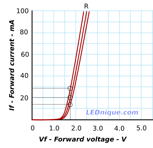
Figure 3. For multiple LEDs of the same colour the situation is a little better – but still not ideal.
Even if all the LEDs are the same colour we can expect some variation in forward current from LED to LED. The variation might be reduced by using LEDs from the same production lot but even the manufacturers don’t rely on this and use “binning” to grade LEDs into matched lots for sensitive applications.
The best approach
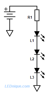
Figure 4. Series connection, if the supply voltage is adequate, ensures the same current through each LED.
Figure 5. For low-voltage applications a single resistor per LED prevents current hogging by the LED with the lowest [latex]V_F[/latex].Finally, the correct way to solve the problem is to series connect for efficiency – so that the same current runs all the LEDs in the string – or, for low-voltage applications, to use a current-limiting resistor per LED.
A bi-colour 2-pin LED can easily be switched to either colour or any blend in between with two GPIO pins.
If two GPIO1 pins are available controlling a 2-pin bi-colour back-to-back LED is simple.
How it works
To light L1, green, switch GPIO1 high and GPIO2 low. Current will flow from left to right.
To light L2, red, switch CPIO2 high and GPIO1 low. Current will flow from right to left.
To cross-fade or mix colours toggle between the two states above. A smooth blend can be obtained by varying the duty cycle.
To fade the LED set both of the outputs high or low for part of the time.
To switch off the LED set both of the outputs high or low. No current will flow and the LED will be dark.
The resistor can, of course, go on either side of the LED.
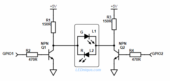
2 x GPIO controlling a higher voltage LED from a 3.3 V GPIO.
This circuit works in a similar manner to the simple one at the top of the page. If the GPIOs are both off then both sides of the LEDs are pulled high and the LEDs are off. To switch on the green Q2 is turned on and R1 sets the current. To switch on the red Q1 is turned on. To blend the colour the GPIOs are toggled alternately.
Note that turning both GPIOs on will turn off the LEDs but waste power through R1 and R2 (but without damage).
The schematic shows a 5 V supply but this could be used for 12 or 24 V LEDs provided the transistor is suitably rated for both voltage and current.
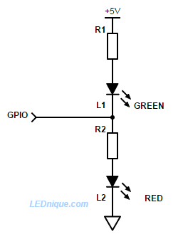
Driving a bi-colour, 2-pin LED with one pin is possible!
A single GPIO pin driving a bi-colour, 2-pin LED.
When GPIO1 pins are in short supply a bi-colour 2-pin LED may seem like a good idea.
It can be done, but is not that efficient.
How it works
When GPIO is low R1 provides current to L2 and the indicator glows red.
When GPIO is high current flows through L1 and R2 to ground and the indicator glows green.
By alternating the GPIO high-low fast enough both LEDs can be illuminated giving an orange colour (since they’re both in the same package). By varying the ‘on’ pulse width a smooth cross-fade can be given from red to green.
If the GPIO is tri-stated (disconnected) the LED will be dark.
Note that this circuit is not very efficient. R1 and R2 pass current to ground always and when the red LED is on R2 is stealing power from it and when the green LED is on R1 is stealing power from it. It may take some experimentation to get this to work.
Figure 1. A single GPIO pin alternating the two LEDs of a common cathode dual LED.
When GPIO1 pins are in short supply a dual red-green common-cathode LED can still be used with the addition of a PNP transistor and base resistor.
How it works
When the GPIO pin is high L1, green, is turned on. There is no bias current for Q1 so it remains off and L2, red, is dark.
When the GPIO pin is low L1 is dark but current flows from the base of Q1 via R3 to the GPIO pin. This turns on Q1 and L2, red, will illuminate.
By alternating the GPIO high-low fast enough both LEDs can be illuminated giving an orange colour (since they’re both in the same package). By varying the ‘on’ pulse width a smooth cross-fade can be given from red to green.
If the GPIO is tri-stated (disconnected) there may be enough leakage current from the base via R3, R1 and L1 to turn Q1 on slightly and illuminate L2, red.
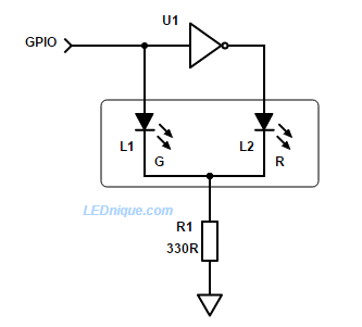
Inverter version
Figure 2. Using an inverter to alternate between two LEDs using one GPIO.
If there is a spare inverter on the board we can reduce component count as shown.
How it works
When the GPIO is high L1, green, is lit. U1 output is low and L2 is dark.
When the GPIO is low L1, green, is dark. U1 output is high and L2, red, is lit.
Note that this circuit shares a common resistor, R1, in the cathode. When L1 is on the cathode will rise to V+ – 2 V, approx., (the supply voltage minus the \(V_F\) of the LED) and the other LED will be reverse biased by that voltage. For supply voltages above 5 V this may cause reverse breakdown of the LED and so the arrangement below is better in that case.
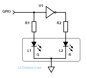
Inverter version for higher voltages
Figure 3. With an additional resistor there is no danger of reverse biasing the LED.
How it works
Operation is the same as Figure 2 but with the cathode firmly connected to ground neither LED is ever reverse biased.
When the output is switched low current will flow from the positive supply via R1 and the L1, green, to the output pin. L1 will illuminate. L2, red, will be shorted out and will be dark.
When the output is switched high current will flow from the pin through R2 and L2. The red LED will illuminate and the green will be dark.
If the output is tri-stated (wired as an input or disconnected by program control) a current will flow through R1, L1, R2, L2 and both LEDs will glow dimly. On a 3.3 V device the voltage wouldn’t be high enough to illuminate both LEDs significantly so they would appear dark.
By rapidly (> 25 Hz should be enough) alternately switching the output high and low while varying the duty-cycle the red and green can be blended to give any colour in between the two.
Figure 2. A SunLED green-red integrated LED package with independent pinouts. See datasheet.Figure 3. RGB LEDs are available in 6-pin versions without common cathodes or anodes. e.g., Kingbright LED LF79WAEMBGMBW, 8 mm, RGB, 20–30 mcd.
Note that to incorporate the 6-pin LED of Figure 3 into the circuit of Figure 1 you would control two of the three LEDs but leave the third unconnected, driven permanently or from another GPIO.
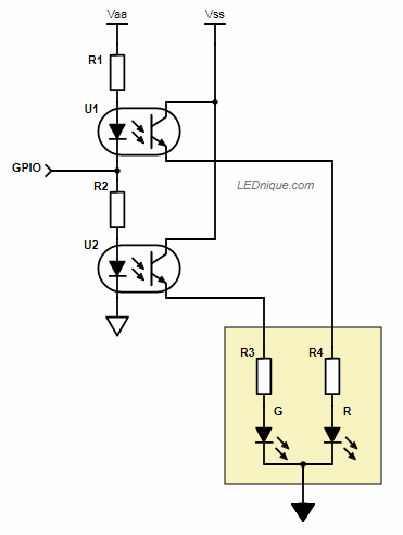
Figure 4. 1 GPIO – 2 opto-isolators.
The same trick can be used to switch isolated or non-isolated loads using opto-isolators. When the GPIO is high U2 will be turned on. When low, U1 will be turned on.
1 switch, 2 LEDs
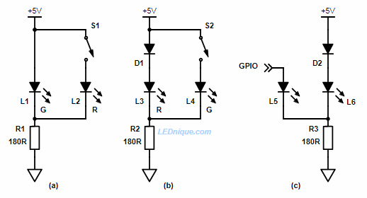
Figure 5. 1 switch or GPIO and 2 LEDs.
In (a) above the green LED is normally lit. There will be about 2.1 V across the LED.
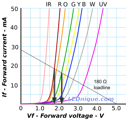
When S1 is closed the red LED will turn on but since it’s forward voltage drop is only about 1.75 V the current in the green will drop very low. A look at the load-line graph shows us why.
Figure 6. Load-line for red and green LEDs in parallel shows that the red drops the voltage enough that little current passes through the green LED.
When the red LED is in circuit the LED voltage drops to 1.75 V or so. At this voltage the green only passes a couple of mA and will be off or dim.
If you want the circuit to operate the other way around as in Figure 5b then you need to induce further voltage drop. D1 achieves this. Now the combination of D1 and L3 will drop about 0.7 + 1.75 = 2.45 V. When the green is switched on there won’t be enough forward voltage to light the red (brightly).
The diode can be added to Figure 1a to reduce current further if the reduced current proves to be too bright.
The circuit will work with a GPIO output as shown in Figure 5c. In this case the additional diode, D2, will almost certainly be required as the GPIO will not reach +5 V when under load.