
An opto-isolator is a component that transfers electrical signals between two isolated circuits by using light. This allows transmission of electrical signals between systems of different voltages with complete electrical isolation up to the rated isolation voltage. A 5 V logic signal, for example, might switch a mains circuit using an opto-isolator without risk of the mains feeding into to the low-voltage logic. 1 kV isolation is common for mains powered circuits.
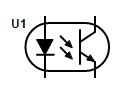
The most common type of opto-isolator consists of an LED and a photo-transistor combined in an opaque package. In operation the photons from the illuminated LED that hit the base-collector junction in the transistor generate electrons and these are injected into the base, turning on the transistor.
Usually opto-isolators transfer digital (on-off) signals, but some techniques allow them to be used with analog signals.
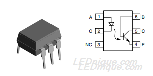
Figure 2 shows a typical pinout for a 6-pin DIL single opto-isolator package. This one makes the transistor’s base available on pin 6 but this is not always the case – particularly on high-density packages.
A basic application
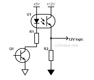
Figure 3 shows a simple application where a 5 V logic signal in one circuit is controlling a 12 V signal in another. When Q1 is switched on U1 LED will illuminate and the collector-emitter resistance will fall to a low value. The 12 V logic level will then switch from low to high.
Note the different ground symbols on the 5 V and 12 V circuits indicating isolated grounds.
Reading the datasheet
The information below is published in the Vishay 4N25 datasheet. As always, in most applications certain parameters become more significant than others. Careful reading of the datasheets and experience will be your guide.
Absolute maximum ratings
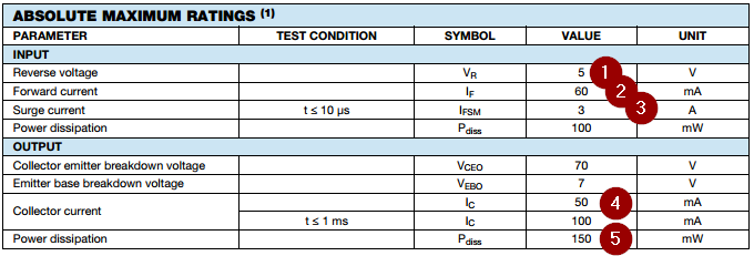
From the Absolute Maximum Ratings section we can see:
(1) The maximum reverse voltage the LED can take is 5 V.
(2) The maximum continuous forward current is 60 mA.
(3) Surprisingly, perhaps, the LED peak current is 3 A but note well that this is for ≤ 10 µs. There will be a recovery time associated with this.
(4) The transistor output is capable of 100 mA continuous.
(5) Watch the output transistor power dissipation: if the transistor is not turned hard-on there will be a voltage drop across it and the power dissipation may rise. e.g., If there is 3 V across the output transistor then the maximum output current will be given by \(I_{max} = \frac {P_{max}}{V_{ce}} = \frac {150m}{3} = 50 \, \mathrm mA\).
Isolation, creepage and clearance
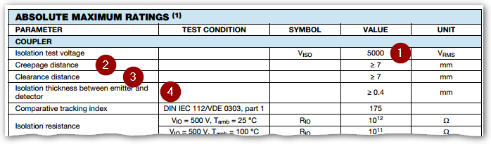
(1) 5,000 V isolation between the input and output.
(2) The creepage distance is 7 mm. This is the shortest distance along the surface of the package between any input and output pin.
See Vishay’s Design Guidelines for Optocoupler Safety Agency Compliance for details on this.
(3) The clearance distance is the shortest distance through the air between the any input and output. Note that in most cases the PCB pad radius will reduce this distance significantly.
(4) The internal insulation thickness.
Input and output specifications
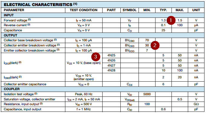
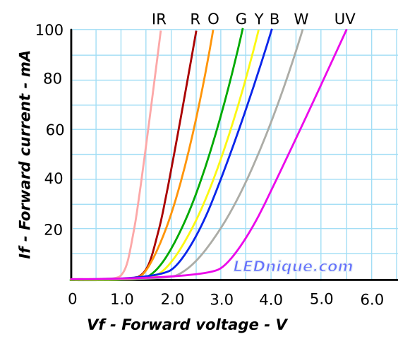
(1) The forward voltage of the LED is only 1.3 V. From this we can infer that it is an infra-red type – see Figure 5 – but this is stated in the description on page 1.
(2) The maximum voltage we can switch with this device is 30 V.
(3) At 10 V there will be up to 50 nA leakage current between the collector and emitter when the LED is dark (unpowered).
Other parameters such as capacitance may be important at high frequencies.
Current transfer ratio
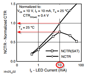
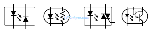
Table 4 and Figure 6 show us that for this device when the LED is run at 10 mA we can expect to get only 2 to 5 mA maximum out of the transistor. If more current is required then further amplification is required – e.g., the Darlington arrangement shown at the top of this page.
In most applications we design the circuit to drive the output transistor into saturation.
Switching characteristics

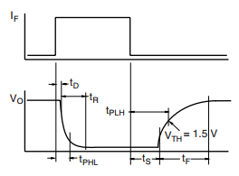
While Table 5 gives the impression that a fixed time delay of 2 µs is given, Figures 7 and 8 show that the situation is more complex.
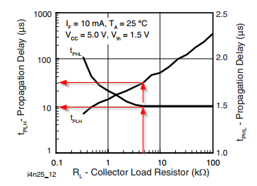
Figure 7 demonstrates that for a 4.7 kΩ load on a 5 V supply we could expect a 10 µs fall time (PHL) (photo-transistor turning on) but a 30 µs rise time (PLH) (photo-transistor turning off). This difference may be enough to cause problems in high frequency circuits or where accurate timing is required.
Other types of opto-isolator
Opto-isolators can be made using LED-photodiode, LED-LASCR, and lamp-photoresistor pairs.
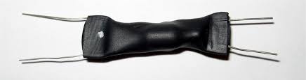
Opto-couplers were used before LEDs were invented. Fender guitar amplifiers, for example, used an old-fashioned neon lamp and light-dependent resistor (LDR) combination in the tremelo circuit of some models.
Alternate terminology
See also: optocoupler, photocoupler, or optical isolator.


