
In certain circumstances the supply voltage is not high enough to light the LED – particularly with blue or white types which have a higher forward voltage. For example, a 3.3 V micro-controller will not light an LED that has a forward voltage of 3.6 V at 20 mA. We can get around this by using a voltage doubler drive circuit.
How it works:
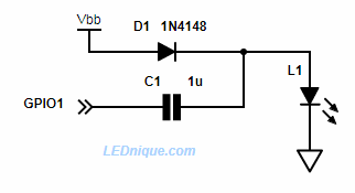
- To light the LED, set the GPIO pin to output mode and then pulse the pin with a square wave. This makes a crude voltage doubler / charge pump.
- D1 charges up the right side of C1 to Vbb (less a fraction of a volt due to its forward voltage drop). This isn’t enough to light the LED.
- When the GPIO pin is switched high the left side of the capacitor is pulled high and this “lifts” the right side high too. When it exceeds the \( V_f \) of L1 charge flows from the capacitor through the LED.
- The LED current limit comes from the fact that the capacitor will transfer a certain amount of charge per pulse, and charge multiplied by frequency (i.e. charge per second) is current. Also your micro’s IO pins will have 20-50 ohm output resistance so you don’t need a resistor.
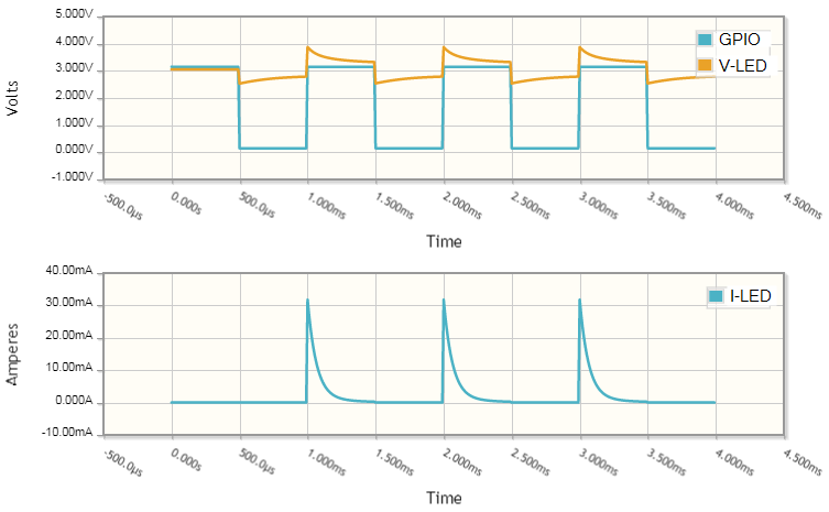
The charge transferred by the capacitor on each pulse is given by \( Q = CV \) where Q is the charge in coulombs, C is the capacitance and V is the voltage across the capacitor. Running on a 3.3 V supply we should allow a little for losses and assume 3 V charge. Therefore the charge per pulse is \( Q = CV = 1\mu \times 3 = 3 \mathrm{\mu C} \) (micro-coulombs).
At 1 kHz the total charge pumped through the circuit will be \( 3\mu \times 1000 = 3000 \mathrm{\mu C} = 3 \ \mathrm{mC} \). This frequency is far above the human eye’s ability to discern flicker.
Current is charge per second so the average current is given by this arrangement is 3 mA. This won’t light the LED very brightly.
We can drive more current through the LED by increasing the frequency. If we run at 5 kHz we should be able to get about 15 mA through it.
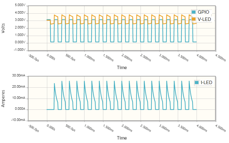
Here we can see that the shape of the current pulses are roughly the same but truncated when the GPIO switches low. As a result the peaks are a little low too.
How much the situation can be optimised depends on several factors including the internal resistance of the GPIO, the supply voltage, the chosen frequency, C1’s value and, of course, \( V_f \) of the LED. Some simulation and trials may be required.
The scheme above is a very economical way to do it – only two very small, cheap parts. Efficiency won’t be that good, but it will light your LED. You can also dim it by adjusting the frequency and, depending on your coding skills, have it fade on and off.
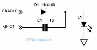
If the circuit of Figure 1 glows when off the modification of Figure 2 should fix it. A second GPIO provides an enable pin. When high the voltage doubler will work as described above. When low the LED will not light as the right side of C1 will not be charged adequately.


