The temptation …
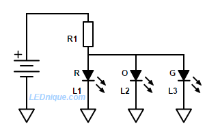
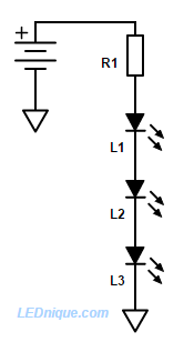
Many beginners ask why LEDs can’t be wired in parallel to share a common current-limiting resistor as shown in Figure 1. Well they can – but it’s usually not a good idea to parallel LEDs directly.
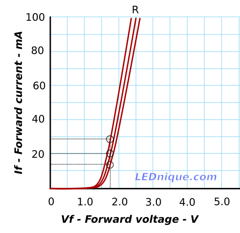
To understand why we need to look at the LED IV1.
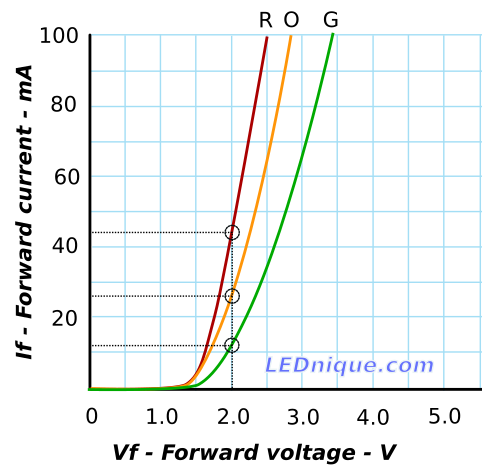
In this example we’ll first consider the case of parallel connection of a red, orange and green LED. If the value of R1 chosen in Figure 1 were to result in a common voltage of 2.0 V applied across each of the three LEDs then we could calculate the expected current through each using Figure 2.
- The green LED has the highest \(V_F\) of the three and at 2 V it will pass about 12 mA. It will be reasonably bright at this current.
- The orange LED has a lower \(V_F\) and it will pass about 27 mA. It will be very bright at this current and would be close to maximum continuous rating for a typical 3 or 5 mm LED. See LED current rating for a typical specification.
- The red LED has the lowest \(V_F\) and it will pass about 44 mA. This is above the 30 mA rating in the datasheet in the article above. The LED will be good and bright – for a time!
But if they’re all the same colour …?
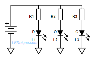
Even if all the LEDs are the same colour we can expect some variation in forward current from LED to LED. The variation might be reduced by using LEDs from the same production lot but even the manufacturers don’t rely on this and use “binning” to grade LEDs into matched lots for sensitive applications.
The best approach