
Opto-triacs summary
- Opto-triacs or solid-state relays (SSR) consist of an infra-red LED and a triac in one package. The LED is switched on and off by a low-power DC control circuit and this switches the triac which can be used to control AC devices up to mains voltages.
- Opto-triacs provide electrical isolation between the control circuit and the AC circuit.
- Opto-triacs are available in “random” and zero-cross types.
- Since the LED portion of the opto-triac is an infra-red LED the series resistor value can be calculated if the required current is known. (Get this value from the device datasheet.)
Safety
Triacs are usually used on mains voltage. This presents a serious risk of electrocution. Working on mains voltage is not recommended for beginners in electronics.
How triacs work
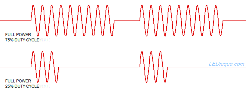
Triacs are semi-conductor switches that can be turned on by a pulse on the gate or trigger pin. Once turned on they stay on until the current drops below the hold-on value. By delaying the turn-on point until some time after the voltage crosses zero volts – the zero-cross point – the voltage can be adjusted although it is no longer sinusoidal.
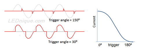
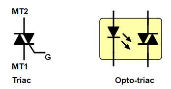
The devices shown in Figure 2 can be used to give variable phase-angle control as shown in Figure 1. (These are sometimes called “random” opto-triacs or SSRs but “random” is a misnomer as usually the trigger point is anything but random and is controlled. What is meant is “variable” trigger-point.)
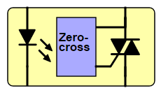
When the LED of the zero-cross opto-triac it turned on the zero-cross detection circuit will wait until the voltage is very close to zero before switching on the triac. This minimises switching noise and electro-magnetic interference (EMI) to neighbouring equipment.
How zero-cross detection works
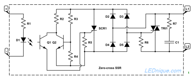
- If \(V_{L1−L2}\) is low (above but close to zero) and Q1 is turned on by photo-action from D1 then SCR1 will be triggered. This in turn will pass enough current through R6 to bring TRI1 gate voltage high enough to trigger.
- When voltage exceeds a certain level Q2 will be biased on. The collector voltage will fall and there won’t be enough to turn on SCR1 even if Q1 subsequently turns on.
The effect is that TRI1 can’t turn on unless it is triggered close to the zero cross.
Further reading
- Phase Control Using Thyristors by Littlefuse.
- Thyristor Theory and Design Considerations Handbook by ON Semiconductor.


