
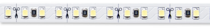
The typical flexible LED strip light is powered from a 12 V supply. This is enough to power several LEDs in series. This is more efficient than connecting them all in parallel since the same current can power three LEDs rather than only one.
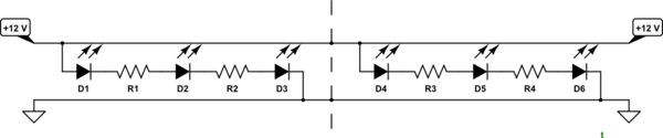
Schematic diagram of strip. Note that cutting in the wrong place will result in one, two or three LEDs not working. In this example two voltage-dropping resistors are used per 3-LED string – presumably to spread the heat-dissipation over two devices.
The 12 V rails run the full length of the strip.
- In each section three LEDs are wired in series with one or two current limiting resistors.
- The strip can be cut at any scissors-marked point without breaking a series string.
Strips can be connected in series but if fed from one end note that the first strip will have to carry the current for all the LEDs and may overheat and fail. Additionally, voltage drop along the line will cause the voltage to droop. For this reason it is better to run wires from each strip straight back to the power supply.
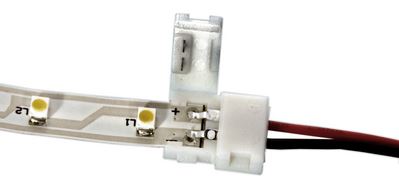
Connections to strips
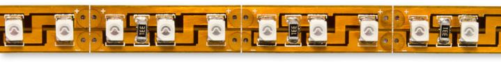
The lowest cost solution is to solder the power leads directly to the flexible LED strip light. The copper pads and wires should be solder tinned and then soldered together. Do not overheat the pads or they will lift from the flexible substrate and will probably break. The downside of this approach is that all of the mechanical stress will be on the solder pads.
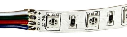
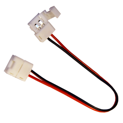
In contrast, the connectors below spread the stress onto the flexible board, are removable. The latter point may be important if you have to replace a strip in an awkward location.
Avoiding voltage drop along strip
A common problem with long lengths of LED strips is that because they are typically powered from one end that the lights get dimmer due to voltage drop along the strip. The strip nearest the power source has to carry the current for nearly all the LEDs and voltage drop is relatively high along the flexible tracks. The LEDs nearest the supply get full voltage but the voltage falls – steeply at first – as we move along the strip. Because the current is decreasing with distance from source the intensity of the further LEDs is relatively constant.
One big help is to power the circuit from both ends. This halves the voltage drop but there may still be a noticable dip in the centre.

With this arrangement the LEDs on the left experience maximum voltage drop on the positive line and none on the negative line. Meanwhile those on the right experience the most drop on the negative and none on the positive while those in the middle experience the same voltage drop on positive and negative.


