The non-linear relationship between current and voltage is important but easy to understand.
In this section we explore the following topics.
IV curves
A device’s IV curve – current versus voltage curve – is a graph of the current that will flow in the device as a function of the voltage across it. As suggested by Ohm’s Law, , the relationship between current and voltage in a resistor is linear. Figure 1 clearly shows that the current increases linearly with increasing … Continue reading "IV curves"
'Resistance' of an LED
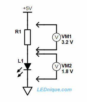
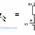
LEDs do not have a linear relationship between current and voltage so they cannot be modeled as simply as a resistor using Ohm’s Law, . We can, however, make a simplification and model them over a range of currents as a combination of a resistor and a voltage source. If we look at a typical … Continue reading "‘Resistance’ of an LED"
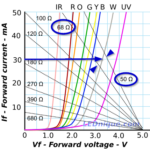
Loadline resistance graphic tool
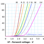
Most LED circuits require a current limiting resistor. The loadline calculator makes resistor selection very simple. Example 1: Chose a resistor to give 20 mA on a yellow LED and 5 V supply. Solution: Choose 20 mA on the If axis. Slide across to the yellow LED curve. Find the nearest loadline: in this case it’s … Continue reading "Loadline resistance graphic tool"
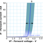
Variations in Vf and "binning"
LEDs’ forward voltage drop varies from device to device and by more than you might think. This causes a few issues for the user. The Lite-On LTST-C170TBKT InGaN blue LED datasheet, for example, shows the forward voltage varies between 2.8 V and 3.8 V at 20 mA. This is quite a variation. The lower value would, just about, allow … Continue reading "Variations in Vf and “binning”"