Dimmable mains LED bulbs

Not all mains bulbs are dimmable. Those that are may require special dimmers to operate. In this article we explain how filament lamp dimmers work and some of the issues that can occur with LED lamps.

Symbol for non-dimmable and dimmable LED lamps.
Symbols for non-dimmable and dimmable LED lamps.


Incandescent lamp dimmer

Incandescent lamp dimmer circuit.
Figure 1. A bare-bones incandescent lamp dimmer circuit.

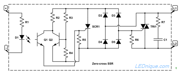
Figure 1 shows a typical triac dimmer for incandescent lamps. Initially the triac, T1, is off.

  • As the mains voltage rises C1 starts to charge up at a rate determined by the setting of R1; the lower the value of R1 the faster C1 charges up.
  • When the voltage on C1 reaches about 20 V the DIAC breaks down and the charge in C1 flows into the trigger of T1 turning it on.
  • One of the triac’s characteristics is that once triggered the triac will remain on until the current falls below the hold-on value which is close to zero (typically about 50 mA).

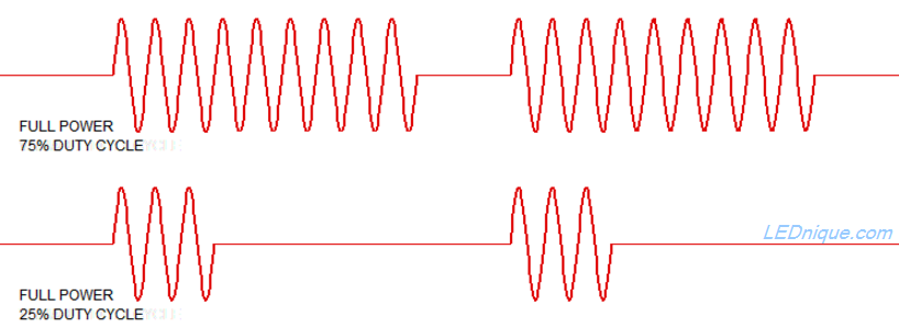
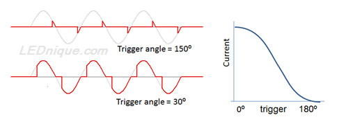
The result is a phase-angle controlled waveform as shown in Figure 2. If the triac is triggered late in the cycle (upper trace) the RMS voltage is low. If triggered early in the cycle (lower trace) the RMS voltage will be high. Note that the response is not linear.

Figure 2. The upper trace shows the trigger delayed close to the end of the cycle. The resultant effective voltage is low. The lower trace shows the trigger close to the start of the cycle. This will result in close to full voltage. The relationship between phase angle delay and resultant RMS voltage is graphed on the right.


Fluorescent lights

As fluorescent lights need a minimum voltage, and both compact fluorescents and LEDs use electronics which rectifies the peak voltage provided, the conventional phase-angle control dimmer fails to dim them.

Ballast fluorescent lights would dim as the voltage reduced a little but then probably flicker and fail to light at all as the tube temperature dropped at further reduced voltage. For high frequency flourescent, CCFL and LED, it all depends on how the control circuitry has been designed.

LED filament bulbs

LED filament lamps look remarkably similar to tungsten filament lamps.

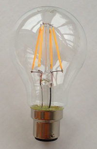
Generally these lamps should work well with dimmers as there are no onboard electronics. Read more about these in LED filament lamps.

Passive LED

Some of the cheap LED mains lamps use a capacative voltage dropper to reduce the voltage and limit the current to the lamps. (A capacitor has a certain ‘impedance’ to AC – its AC resistance – given by \( Z = \frac {1}{2 \pi f C} \) where f is the mains frequency, 50 or 60 Hz and C is the capacitance in F.)
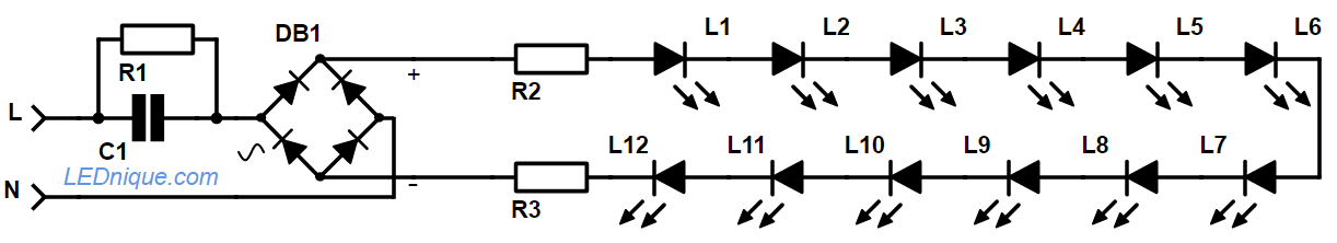
Capacitive dropper power-supply LED bulb.
A typical arrangement for a cheap capacitive dropper power-supply LED bulb.

How it works:

  • C1 is chosen to limit the current to the rectifier.
  • R1 is a high value and has no function in the circuit other than to discharge C1 when the power is switched off.
  • Bridge rectifier, DB1, converts to DC.
  • R2 and 3, in conjunction with C1, set the current through the LEDs.
  • Note that since all are in series that the same small current powers them all.

These bulbs should respond well to a dimmer as there are no components storing charge during the mains cycle. The problem is that it is almost impossible to tell without a test.

Capacitor dropper lamp with smoothing
If the manufacturer has included a smoothing capacitor a further complication arises.

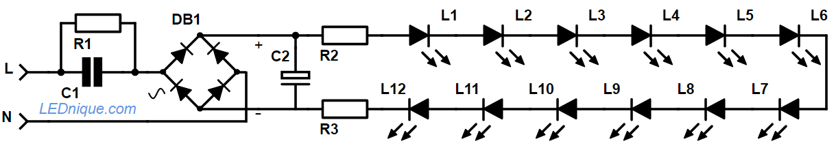
Note that if a smooting capacitor such as C2 is included after the rectifier that the dimmer won’t appear to do anything until the control is adjusted below 50%. This is because the capacitor charges up fully at peak mains even if it hasn’t been on up to 90° into the half-cycle. (See Figure 1.) From 90° to 180° the peak voltage drops so the lamp will dim in proportion.

Constant power / current lamps

Lamps designed to work at full output over a wide range of input voltages will not behave well with dimmers. Typically these will use an internal switched mode power supply which will attempt to keep the LEDs running at designed current until the voltage goes below the minimum specified.

Since the power (\( P = VI \)) is constant across the range of supply voltages the current will increase as the voltage decreases. If the supply voltage drops below the minimum specification the power supply can no longer maintain the output current. At this point the LEDs may dim or flicker or just go out.

Smart dimmable bulbs

Note that some dimmable LED bulbs are available. They rectify the peak voltage, take their control input as the width of the pulse from the TRIAC dimmer, and program their current output accordingly. Some clever types even change their colour temperature according to the dimmer setting, cool white when full on, and warm white when dimmed.

For successful dimming you need to match the dimmer and lamp or power-supply.

Opto-triacs, solid-state relays (SSR), zero-cross and how they work

Opto-triacs summary

  • Opto-triacs or solid-state relays (SSR) consist of an infra-red LED and a triac in one package. The LED is switched on and off by a low-power DC control circuit and this switches the triac which can be used to control AC devices up to mains voltages.
  • Opto-triacs provide electrical isolation between the control circuit and the AC circuit.
  • Opto-triacs are available in “random” and zero-cross types.
  • Since the LED portion of the opto-triac is an infra-red LED the series resistor value can be calculated if the required current is known. (Get this value from the device datasheet.)

Safety

Triacs are usually used on mains voltage. This presents a serious risk of electrocution. Working on mains voltage is not recommended for beginners in electronics.

How triacs work

Triacs are semi-conductor switches that can be turned on by a pulse on the gate or trigger pin. Once turned on they stay on until the current drops below the hold-on value. By delaying the turn-on point until some time after the voltage crosses zero volts – the zero-cross point – the voltage can be adjusted although it is no longer sinusoidal.

Figure 1. The upper trace shows the trigger delayed close to the end of the cycle. The resultant effective voltage is low. The lower trace shows the trigger close to the start of the cycle. This will result in close to full voltage. The relationship between phase angle delay and resultant RMS voltage is graphed on the right.
Triac and opto-triac.
Figure 2. Schematic symbols for a discrete triac and an opto-triac. Note that since the opto triac is optically triggered it (usually) does not have a gate or trigger pin.

The devices shown in Figure 2 can be used to give variable phase-angle control as shown in Figure 1. (These are sometimes called “random” opto-triacs  or SSRs but “random” is a misnomer as usually the trigger point is anything but random and is controlled. What is meant is “variable” trigger-point.)

A zero-cross opto-triac or SSR.
Figure 4. A zero-cross opto-triac or SSR.

When the LED of the zero-cross opto-triac it turned on the zero-cross detection circuit will wait until the voltage is very close to zero before switching on the triac. This minimises switching noise and electro-magnetic interference (EMI) to neighbouring equipment.

Variable duty-cycle AC control waveform.
Figure 4. With zero-cross switching the result is that the waveform consists of multiple complete half-cycles.


How zero-cross detection works

Zero-cross opto-triac.
Figure 5. Internals of a zero-cross detection circuit based on the G3MB-202P with 5V input.
  • If \(V_{L1L2}\) is low (above but close to zero) and Q1 is turned on by photo-action from D1 then SCR1 will be triggered. This in turn will pass enough current through R6 to bring TRI1 gate voltage high enough to trigger.
  • When voltage exceeds a certain level Q2 will be biased on. The collector voltage will fall and there won’t be enough to turn on SCR1 even if Q1 subsequently turns on.

The effect is that TRI1 can’t turn on unless it is triggered close to the zero cross.

Further reading