An LED can be used as a simple stepper motor continuity tester. Motors act as generators when driven and a typical stepper motor will generate a low voltage / low current output when spun by hand. This is enough to light an LED.
The technique can be used to figure out motor winding pairs and continuity.
Other methods of checking windings are:
Short one winding. (In the video example that would require replacing the LED with a link.) You should feel a very marked increase in resistance to rotation and feel “cogging” as each tooth of the rotor passes a pole. Repeat for the other winding.
Use a multimeter. This will be more useful than the video LED test in identifying the windings in, for example, centre-tapped uni-polar motors as each coil’s end to end resistance will be double that of centre to end resistance. It also allows comparison between windings.
Infrared (or infra-red) LEDs emit light at a wavelength invisible to the naked eye. This makes it difficult to tell whether the LED is working or not – TV remote controls with suspect battery or bad connections being a prime example. Fortunately most digital cameras are sensitive to IR and can be used to test infrared LEDs.
View the LED through the digital camera. When the LED is lit most cameras will display a purple-tinted image of the LED.
The purple hue is interesting.
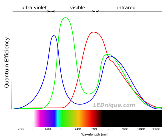
Figure 1. Typical camera chip spectral response.
We can see that the blue sensors respond well in the blue region of the spectrum, and the green and red to theirs. The surprise is that they all respond well in the IR part of the spectrum. The colour rendered by the camera looking at the IR LED will depend on the relative strengths of the colours at the frequency of interest. If we examined a 900 nm IR LED we could expect a blue tinge on the image as the blue sensor is more efficient at this wavelength.
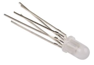
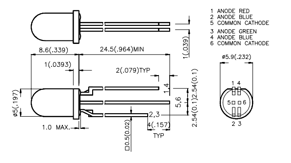
Most LEDs are simple single device with two leads but packages with two or more LEDs are common and there are various LED pinouts in use.
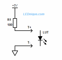
Simple LED test circuit
Simple LED test circuit. ‘LUT’ stands for ‘LED under test’!
Most LEDs will light at less than 5 V and can tolerate 5 V reverse voltage. A 5 V supply is available from a USB supply or, for example, an Arduino. You can use a higher voltage such as a 9 V battery and double the value of R1 but you might damage sensitive devices on reverse voltage.
See Testing unknown LEDs for more on this topic.
Note that LEDs usually have no two pins the same length. This is for two reasons:
It helps identify the pins.
It helps during assembly as pins can be inserted one at a time from longest to shortest without having to align all the pins simultaneously.
2-pin
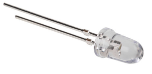
The most common type of LED is the 2-pin, 5 mm, round lens type. Generally these are a single LED. Polarity is indicated by the long lead (+ / anode) or the flat on one side of the base (- / cathode).
A typical 2-pin LED.The two-pin package can contain a single or two back-to back LEDs.
Be aware that bi-colour LEDs are also sold in this package. Some are dual-colour so that reversing the current through them changes the colour. Others may have both LEDs the same colour and this can be useful in AC applications as it can conduct on both cycles of the mains and eliminates the need for a rectifier.
The bi-colour LED’s datasheet will specify which way round to connect to ensure the correct colour.
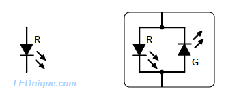
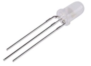
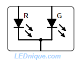
3-pin
A 3-pin LED.
The three-pin LED is usually a pair of LEDs of different colours sharing a common anode or common cathode. Either LED can be turned on independently or blended to create a combination.
A bi-colour, 3-pin, common-cathode LED.
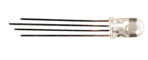
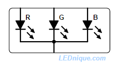
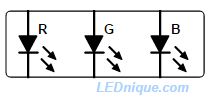
4-pin
The popular RGB, 4-pin, LED allows generation of colours across the visible spectrum.
The 4-pin package is most commonly seen on RGB (red-greeen-blue) LEDs. Common cathode and common anode versions are available.
An RGB LED in a 4-pin package. Note that this one has a common cathode.
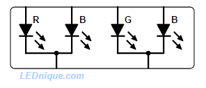
6-pin
RGB with individual pinouts allows common anode, common cathode configuration as well as series connection of the LEDs.
When the number of pins reaches six all sorts of strange variations are possible. One sensible one is to bring out each LED anode and cathode on individual pins. This allows a single part to be used for common anode, common cathode and series LED configurations.
A slightly strange 6-pin, RB-GB, LED, has two separate 3-pin LEDs in one package.
This package consists of a red-blue pair and a green-blue pair in one package. Note two, independent common cathodes.Kingbright LF5WAEMBGMBW, 6-pin, RB-GB LED has two 3-pin LEDs in one package. Both have a blue LED. Note the pin length orientation clue.
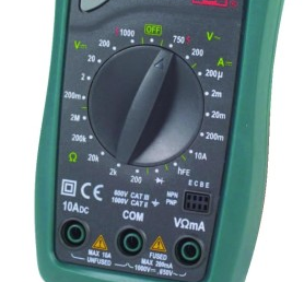
Maplin’s N19BW is economically priced multimeter with manual range selection.
For any electronics work a multimeter is essential. At a minimum you require a meter that can measure volts DC and AC, amps DC and AC and ohms. Most digital meters now have a diode test function and a continuity tester with audible beeper.
If you intend to pursue electronics as a hobby or profession it is well worth purchasing a good quality multimeter. With a little care it will last years or decades.
Choosing a multimeter
For typical electronics projects the most frequent measurements will be as shown below.
Measurement
Range
Notes
DC volts
Up to 20 V DC.
The majority of electronics runs at less than 20 V DC. Micro-controllers run at 5 V or less. Auto electrics are 12 V or 24 V for trucks and busses.
AC volts
Up to 240 V AC
Checking mains voltage is a common requirement. This will be 120 or 230/240 V depending on your location. Get a meter and leads rated for three times this. See separate notes below on true RMS measurements.
Resistance
200 Ω to 20 MΩ
A 200 Ω range will give resolution to 0.1 Ω which is good enough for most applications.
DC current
200 µA to 2000 mA
This will cover most non-power applications.
DC current
10 A
Useful for high-current applications, batteries, lamps, etc.
AC current
This is not often required. Meters usually have some AC measurement ranges. Again, see the true RMS notes below.
Capacitance
Useful but not essential.
Inductance
Again, useful but not essential.
True RMS
A multimeter can be assumed to be “average responding” to AC waveforms unless stated as being a “True RMS” type. An average responding multimeter will only meet its specified accuracy on AC volts and amps for purely sinusoidal waveforms. A True RMS responding multimeter on the other hand will meet its specified accuracy on AC volts and current with any waveform type up to a specified crest factor1. Read the meter datasheet carefully to understand exactly what voltage ranges, crest factor range and frequency range is being specified.
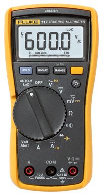
Professional quality multimeter
Professional quality multimeters are made by a large number of manufacturers including Fluke, Robin, Kiethley, Keysight Technologies, Tektronix and many, many more.
The Fluke 117 multimeter covers the basics in a robust multimeter.
Fluke has a reputation for well-built good quality test equipment. The 11x range includes several models with the basic ranges required by any electrical / electronics technician. The 117 pictured above has several additional features including frequency measurement, capacitance, min/max recording, display hold and manual range select.
The 117, with some others in the range, feature a LoZ or low-impedance auto-voltage range. Most digital multimeters have an input impedance of 10 MΩ which is high enough to enable it to pick up ghost voltages on non-energised wiring located in close proximity to energised wiring. This condition forms a capacitor and allows capacitive coupling between the energised wiring and the adjacent dead wiring. The LoZ range places a low-impedance load across the probes to shunt the stray voltage and give a zero reading.
The Fluke 117 DMM also includes the built-in VoltAlert non-contact voltage function. Located on the top of the meter above the LCD display, it’s another feature handy for detecting the invisible. The VoltAlert function detects the presence of ac voltage, sounds an audible tone and activates a red LED indicator light on the top center of the LCD display.
Quality versus features
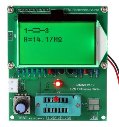
For a given budget I recommend a basic meter with higher specifications and build quality rather than a budget meter with additional features. The better meter should last a lifetime and the additional features can be covered with a multi-function component tester such as the EZM328 for very little additional money.
Multi-component testers such as the EZM328 are very economical and can test resistors, capacitors, inductors, diodes, LEDs, and transistors. They are particularly useful for measuring capacitor equivalent series resistance (ESR).