In this article we examine various failure modes of LEDs including reverse voltage, due to accidental reverse connection, AC powered and multiplexed displays.
Reverse voltage
Almost all LEDs can withstand 5 V reverse voltage. (We rely on this to avoid damaging LEDs in Testing unknown LEDs.) If you try your own reverse voltage limit testing you may find that most have higher actual reverse voltage breakdown voltages of 12 to 70 V. It would be unwise to depend on this in a design project, however, as it is not guaranteed by the manufacturer and could change from batch to batch or vendor to vendor.
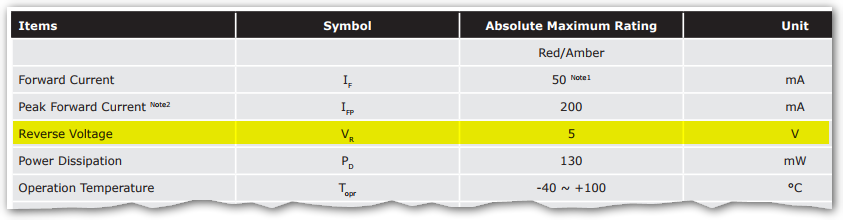
The reverse voltage, \(V_R\) specification in the datasheet above is the minimum value that is guaranteed by the manufacturer. The actual value may be many times that.
In most circuits LEDs are not subject to reverse voltages but there are several cases where, by design, they are.
AC indicators
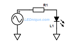
The figure above will work for peak AC voltages up to the reverse breakdown voltage of the LED. For reliable design this means that for a sinusoidal voltage the peak voltage applied should be \(\frac {V_R}{\sqrt 2}\). For a \(V_R\) of 5 V LED this is only 3.5 V RMS.
For a given RMS current through the LED on positive half-cycles set \(R1 = \frac {V_{AC} – V_f}{I} \) (approximately) where \( V_F \) is the forward voltage of the LED. The average current over the full cycle will be half that.
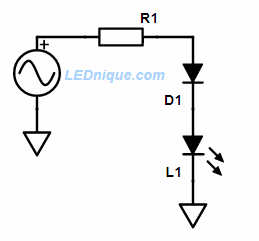
This circuit will work for low AC voltages. The problem is that diodes and LEDs have reverse leakage current. The one with the higher leakage will cause the other to experience more than its fair share of the applied AC voltage. If this exceeds the reverse breakdown of the LED then it may perish.
For a given RMS current through the LED on positive half-cycles set \(R1 = \frac {V_{AC} – V_f – 0.7}{I} \) (approximately) where \( V_F \) is the forward voltage of the LED and 0.7 V is the forward voltage of the diode. The average current over the full cycle will be half that.
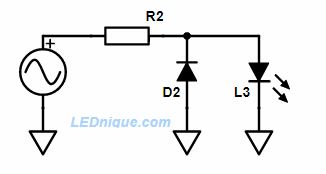
D2 in this arrangement limits the reverse voltage across L3 to only 0.7 V. The down-side is that R2 passes current on both half-cycles which decreases the efficiency as no useful work is done.
For a given RMS current through the LED on positive half-cycles set \(R1 = \frac {V_{AC} – V_f}{I} \) (approximately) where \( V_F \) is the forward voltage of the LED. The average current over the full cycle will be half that.
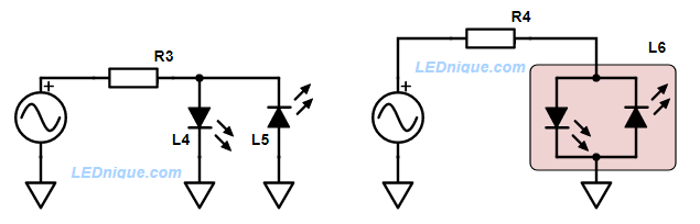
This circuit replaces the diode, D2, of the previous circuit with an LED. L4 and L5 may be both in the same 2-pin package as shown in LED pinouts and opto-isolators.
For a given RMS current through each LED on alternating half-cycles set \(R1 = \frac {V_{AC} – V_f}{I} \) (approximately) where \( V_F \) is the forward voltage of the LED.
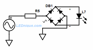
Where a circuit must use only one LED and minimum flicker is required then this circuit will full-wave rectify the current feeding the LED. It will never experience reverse voltage.
For a given RMS current through the LED set \(R5 = \frac {V_{AC} – V_f – 1.4}{I} \) (approximately) where \( V_F \) is the forward voltage of the LED and 1.4 V is the forward voltage of two diodes.
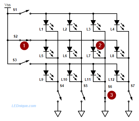
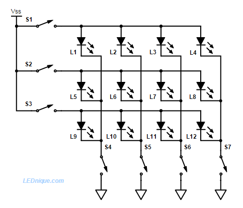
Multiplexed displays
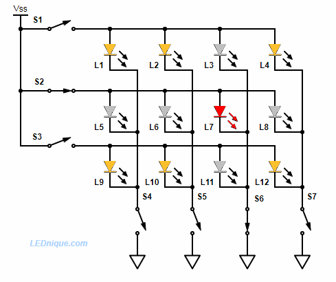
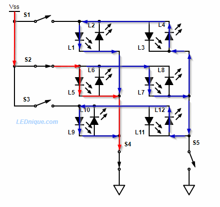
In the figure above S2 and S6 are closed and D7 (shown in red) is lit. Meanwhile L5, 6 and 8 are forward biased (shown in grey) and raise the voltage on the S4, 5 and 7 lines. The multiplexed display relies on the remainder of the LEDs (shown in yellow) don’t break down due to the reverse voltage. For this reason most multiplexed displays use low voltages.
In large displays each LED might consist of a string of series connected LEDs. This requires a higher voltage to drive the display but the reverse voltage is divided across the chain of LEDs so the individual LED’s \(V_R\) is not exceeded.
Flashing LED failure
Flashing, or intermittent connections causing the led to turn on and off, is a typical failure mode of LEDs which are cheaply constructed, physically damaged, or forced with a higher current. When this happens, the LEDs can go through thermal expansion which breaks the internal connection. On cooling, which causes the connection to reconnect, the LEDs may illuminate again. On expansion, etc., the connection breaks again and the cycle continues resulting in flashing. Bond wire breakages can give similar results as can internal shorts of the LED substrate material. This can also lead to LEDs flashing between different brightness.
In badly designed products with parallel LEDs, when some die the rest of your parallel LEDs will get a higher current which will lead them to die as well.