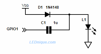
In certain circumstances the supply voltage is not high enough to light the LED – particularly with blue or white types which have a higher forward voltage. For example, a 3.3 V micro-controller will not light an LED that has a forward voltage of 3.6 V at 20 mA. We can get around this by using a voltage doubler drive circuit.
Figure 1. GPIO voltage booster.
How it works:
To light the LED, set the GPIO pin to output mode and then pulse the pin with a square wave. This makes a crude voltage doubler / charge pump.
D1 charges up the right side of C1 to Vbb (less a fraction of a volt due to its forward voltage drop). This isn’t enough to light the LED.
When the GPIO pin is switched high the left side of the capacitor is pulled high and this “lifts” the right side high too. When it exceeds the \( V_f \) of L1 charge flows from the capacitor through the LED.
The LED current limit comes from the fact that the capacitor will transfer a certain amount of charge per pulse, and charge multiplied by frequency (i.e. charge per second) is current. Also your micro’s IO pins will have 20-50 ohm output resistance so you don’t need a resistor.
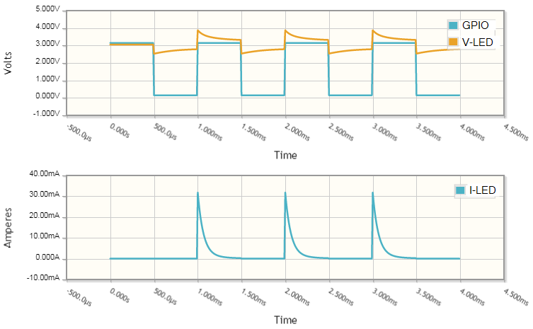
The charge transferred by the capacitor on each pulse is given by \( Q = CV \) where Q is the charge in coulombs, C is the capacitance and V is the voltage across the capacitor. Running on a 3.3 V supply we should allow a little for losses and assume 3 V charge. Therefore the charge per pulse is \( Q = CV = 1\mu \times 3 = 3 \mathrm{\mu C} \) (micro-coulombs).
At 1 kHz the total charge pumped through the circuit will be \( 3\mu \times 1000 = 3000 \mathrm{\mu C} = 3 \ \mathrm{mC} \). This frequency is far above the human eye’s ability to discern flicker.
Current is charge per second so the average current is given by this arrangement is 3 mA. This won’t light the LED very brightly.
Simulation of GPIO voltage doubler running at 1 kHz. The LED current peaks at about 30 mA but the average is more like 3 mA.
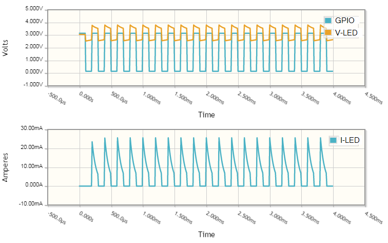
We can drive more current through the LED by increasing the frequency. If we run at 5 kHz we should be able to get about 15 mA through it.
GPIO voltage doubler running at 5 kHz.
Here we can see that the shape of the current pulses are roughly the same but truncated when the GPIO switches low. As a result the peaks are a little low too.
How much the situation can be optimised depends on several factors including the internal resistance of the GPIO, the supply voltage, the chosen frequency, C1’s value and, of course, \( V_f \) of the LED. Some simulation and trials may be required.
The scheme above is a very economical way to do it – only two very small, cheap parts. Efficiency won’t be that good, but it will light your LED. You can also dim it by adjusting the frequency and, depending on your coding skills, have it fade on and off.
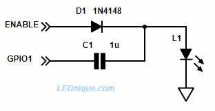
GPIO voltage booster with enable.
If the circuit of Figure 1 glows when off the modification of Figure 2 should fix it. A second GPIO provides an enable pin. When high the voltage doubler will work as described above. When low the LED will not light as the right side of C1 will not be charged adequately.
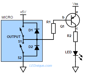
Figure 1. On the face of it, this looks like a reasonable means of achieving a high-side switch. But watch those diodes!
The NPN common emitter configuration makes it easy to make a low-side to switch loads connecte to positive supply. It seems logical to assume that a PNP transistor could provide a mirrored circuit to make a simple high-side switch. The circuit of Figure 1 will work fine provided that \( V_{SS} \leq V_{MICRO} \) (or whatever voltage the micro is running on).
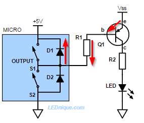
Figure 2. The protection diodes on most logic chips creates a sneak-path to positive supply. This will keep the PNP transistor permanently turned on and may damage the chip.
If If \( V_{SS} > V_{MICRO} \) then the output protection diodes built into the chip provide a sneak path for the base current. The e-b junction of Q1 will be forward biased and current will flow through it, R1 and D1 to the micro supply. Q1 will turn on and LED will light and will not switch off.
We can fix this at the expense of adding an NPN low-side switch.
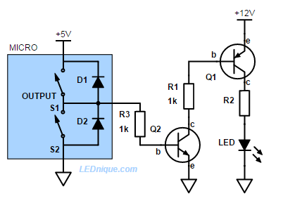
Figure 3. To drive a high-side transistor from a GPIO pin we need a level translator. An NPN transistor does the job nicely.
In Figure 3 the micro drives Q2 as in a normal NPN low-side switch. When Q2 is turned on current will flow from the base of Q1, through R1 and Q2 to ground. Q1 will turn on and the LED will light.
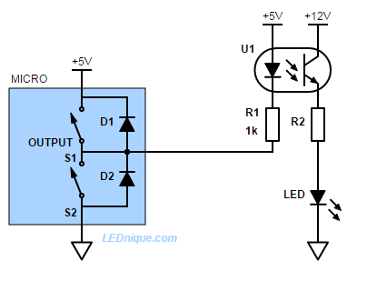
Figure 4. An opto-isolated high-side driver.
In Figure 4 the problem has been solved by using an opto-isolator. Now there is no chance of the 12 V supply back-feeding into the micro.
Note that in this example the grounds are common between the two circuits. They could, however, be separated for complete isolation. See “A basic application” on Opto-isolators – intro for an example.
1 GPIO, 2 LEDs A single GPIO pin can be used to light two LEDs. How it works When the output is switched low current will flow from the positive supply via R1 and the L1, green, to the output pin. L1 will illuminate. L2, red, will be shorted out and will be dark. When the … Continue reading "One switch or GPIO / multiple LEDs"
Driving a bi-colour LED with one pin is possible! When GPIO pins are in short supply a dual red-green common-cathode LED can still be used with the addition of a PNP transistor and base resistor. How it works When the GPIO pin is high L1, green, is turned on. There is no bias current for … Continue reading "1 GPIO, bi-colour LED, common cathode"
Driving a bi-colour, 2-pin LED with one pin is possible! When GPIO pins are in short supply a bi-colour 2-pin LED may seem like a good idea. It can be done, but is not that efficient. How it works When GPIO is low R1 provides current to L2 and the indicator glows red. When GPIO is … Continue reading "1 GPIO, bi-colour, 2-pin LED"
If two GPIO pins are available controlling a 2-pin bi-colour back-to-back LED is simple. How it works To light L1, green, switch GPIO1 high and GPIO2 low. Current will flow from left to right. To light L2, red, switch CPIO2 high and GPIO1 low. Current will flow from right to left. To cross-fade or mix colours toggle between … Continue reading "2 GPIO, 1 bi-colour 2-pin LED"
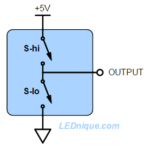
Most micro-controllers and logic families have output stages which can connect the output to the positive supply or to ground. This allows the micro to put a definite ‘high’ (+5 V in this example) onto the output or a definite ‘low’ (ground) rather than let it float which could cause problems if the output is feeding … Continue reading "High-side versus low-side switching"
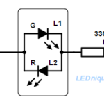
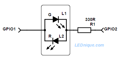
A bi-colour 2-pin LED can easily be switched to either colour or any blend in between with two GPIO pins.
If two GPIO1 pins are available controlling a 2-pin bi-colour back-to-back LED is simple.
How it works
To light L1, green, switch GPIO1 high and GPIO2 low. Current will flow from left to right.
To light L2, red, switch CPIO2 high and GPIO1 low. Current will flow from right to left.
To cross-fade or mix colours toggle between the two states above. A smooth blend can be obtained by varying the duty cycle.
To fade the LED set both of the outputs high or low for part of the time.
To switch off the LED set both of the outputs high or low. No current will flow and the LED will be dark.
The resistor can, of course, go on either side of the LED.
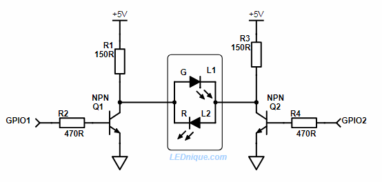
2 x GPIO controlling a higher voltage LED from a 3.3 V GPIO.
This circuit works in a similar manner to the simple one at the top of the page. If the GPIOs are both off then both sides of the LEDs are pulled high and the LEDs are off. To switch on the green Q2 is turned on and R1 sets the current. To switch on the red Q1 is turned on. To blend the colour the GPIOs are toggled alternately.
Note that turning both GPIOs on will turn off the LEDs but waste power through R1 and R2 (but without damage).
The schematic shows a 5 V supply but this could be used for 12 or 24 V LEDs provided the transistor is suitably rated for both voltage and current.
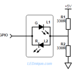
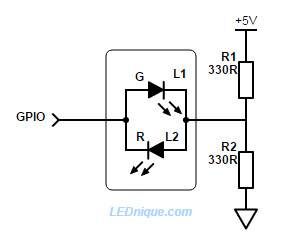
Driving a bi-colour, 2-pin LED with one pin is possible!
A single GPIO pin driving a bi-colour, 2-pin LED.
When GPIO1 pins are in short supply a bi-colour 2-pin LED may seem like a good idea.
It can be done, but is not that efficient.
How it works
When GPIO is low R1 provides current to L2 and the indicator glows red.
When GPIO is high current flows through L1 and R2 to ground and the indicator glows green.
By alternating the GPIO high-low fast enough both LEDs can be illuminated giving an orange colour (since they’re both in the same package). By varying the ‘on’ pulse width a smooth cross-fade can be given from red to green.
If the GPIO is tri-stated (disconnected) the LED will be dark.
Note that this circuit is not very efficient. R1 and R2 pass current to ground always and when the red LED is on R2 is stealing power from it and when the green LED is on R1 is stealing power from it. It may take some experimentation to get this to work.
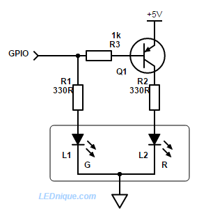
Figure 1. A single GPIO pin alternating the two LEDs of a common cathode dual LED.
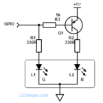
When GPIO1 pins are in short supply a dual red-green common-cathode LED can still be used with the addition of a PNP transistor and base resistor.
How it works
When the GPIO pin is high L1, green, is turned on. There is no bias current for Q1 so it remains off and L2, red, is dark.
When the GPIO pin is low L1 is dark but current flows from the base of Q1 via R3 to the GPIO pin. This turns on Q1 and L2, red, will illuminate.
By alternating the GPIO high-low fast enough both LEDs can be illuminated giving an orange colour (since they’re both in the same package). By varying the ‘on’ pulse width a smooth cross-fade can be given from red to green.
If the GPIO is tri-stated (disconnected) there may be enough leakage current from the base via R3, R1 and L1 to turn Q1 on slightly and illuminate L2, red.
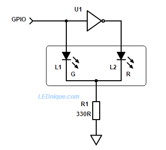
Inverter version
Figure 2. Using an inverter to alternate between two LEDs using one GPIO.
If there is a spare inverter on the board we can reduce component count as shown.
How it works
When the GPIO is high L1, green, is lit. U1 output is low and L2 is dark.
When the GPIO is low L1, green, is dark. U1 output is high and L2, red, is lit.
Note that this circuit shares a common resistor, R1, in the cathode. When L1 is on the cathode will rise to V+ – 2 V, approx., (the supply voltage minus the \(V_F\) of the LED) and the other LED will be reverse biased by that voltage. For supply voltages above 5 V this may cause reverse breakdown of the LED and so the arrangement below is better in that case.
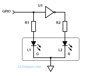
Inverter version for higher voltages
Figure 3. With an additional resistor there is no danger of reverse biasing the LED.
How it works
Operation is the same as Figure 2 but with the cathode firmly connected to ground neither LED is ever reverse biased.
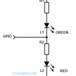
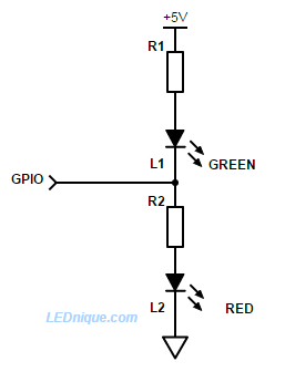
When the output is switched low current will flow from the positive supply via R1 and the L1, green, to the output pin. L1 will illuminate. L2, red, will be shorted out and will be dark.
When the output is switched high current will flow from the pin through R2 and L2. The red LED will illuminate and the green will be dark.
If the output is tri-stated (wired as an input or disconnected by program control) a current will flow through R1, L1, R2, L2 and both LEDs will glow dimly. On a 3.3 V device the voltage wouldn’t be high enough to illuminate both LEDs significantly so they would appear dark.
By rapidly (> 25 Hz should be enough) alternately switching the output high and low while varying the duty-cycle the red and green can be blended to give any colour in between the two.
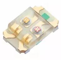
Figure 2. A SunLED green-red integrated LED package with independent pinouts. See datasheet.Figure 3. RGB LEDs are available in 6-pin versions without common cathodes or anodes. e.g., Kingbright LED LF79WAEMBGMBW, 8 mm, RGB, 20–30 mcd.
Note that to incorporate the 6-pin LED of Figure 3 into the circuit of Figure 1 you would control two of the three LEDs but leave the third unconnected, driven permanently or from another GPIO.
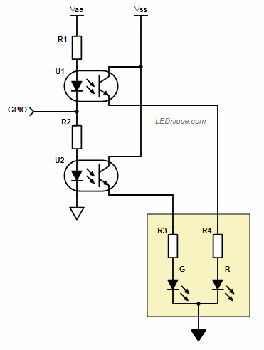
Figure 4. 1 GPIO – 2 opto-isolators.
The same trick can be used to switch isolated or non-isolated loads using opto-isolators. When the GPIO is high U2 will be turned on. When low, U1 will be turned on.
1 switch, 2 LEDs
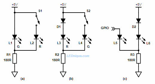
Figure 5. 1 switch or GPIO and 2 LEDs.
In (a) above the green LED is normally lit. There will be about 2.1 V across the LED.
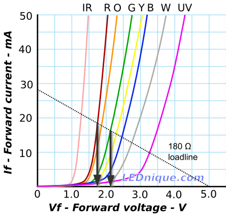
When S1 is closed the red LED will turn on but since it’s forward voltage drop is only about 1.75 V the current in the green will drop very low. A look at the load-line graph shows us why.
Figure 6. Load-line for red and green LEDs in parallel shows that the red drops the voltage enough that little current passes through the green LED.
When the red LED is in circuit the LED voltage drops to 1.75 V or so. At this voltage the green only passes a couple of mA and will be off or dim.
If you want the circuit to operate the other way around as in Figure 5b then you need to induce further voltage drop. D1 achieves this. Now the combination of D1 and L3 will drop about 0.7 + 1.75 = 2.45 V. When the green is switched on there won’t be enough forward voltage to light the red (brightly).
The diode can be added to Figure 1a to reduce current further if the reduced current proves to be too bright.
The circuit will work with a GPIO output as shown in Figure 5c. In this case the additional diode, D2, will almost certainly be required as the GPIO will not reach +5 V when under load.