LEDs’ forward voltage drop varies from device to device and by more than you might think. This causes a few issues for the user.
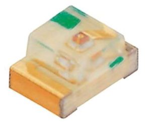
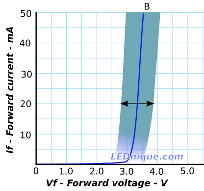
The Lite-On LTST-C170TBKT InGaN blue LED datasheet, for example, shows the forward voltage varies between 2.8 V and 3.8 V at 20 mA. This is quite a variation. The lower value would, just about, allow operation with a low value series resistor at 3.3 V whereas the 3.8 V sample might not turn on very brightly. On higher voltages control of the current by series resistor would vary for different LEDs. (See Simple constant-current driver for a work-around for this.)
The problem is likely to be caused by difficulty in controlling part of the manufacturing process.
Looking at the datasheet we can see that the forward voltage isn’t the only thing affected.
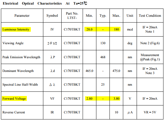
From Table 1 above we can see that the luminous intensity varies from 28 mcd to 180 mcd at 20 mA. This is more than a factor of six in variation! If a random selection of these parts is connected in series the brightness could vary wildly despite all being fed with the same current.
The solution adopted by the manufacturer is “binning”. This means that the LEDs are tested and graded after manufacture and separated into various “bins” depending on one of the parameters.
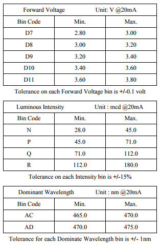
In this case the customer has the choice of selecting parts graded by forward voltage, luminous intensity or dominant wavelength. There is no hint about what the relationship is, for example, between various luminous intensities and the forward voltage. The customer is expected to decide what is important for their application – even brightness, forward voltage or dominant wavelength – and order accordingly. The customer will pay a premium for binned LEDs.
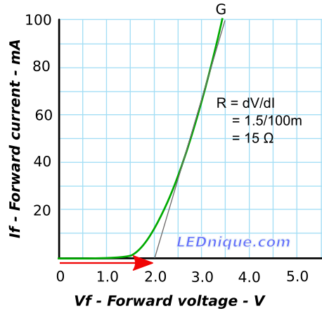
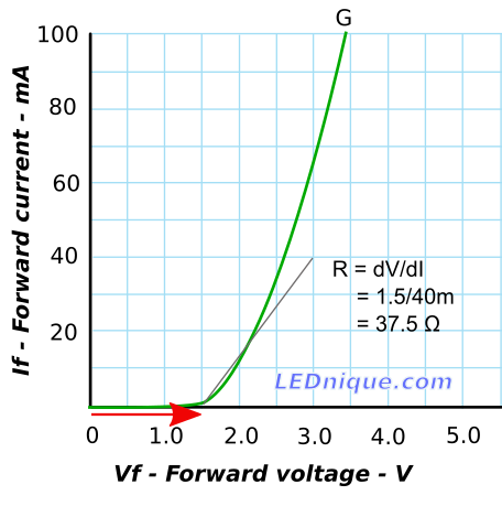
When fed by simple resistor current limiters the current through each LED will vary inversely with \(V_f\) as there will be more voltage dropped across the LED and less across the resistor. (With lower V there will be lower I.)
This issue can be solved with a constant current power supply.