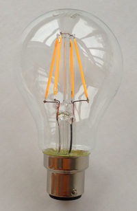
LED filament lamps look remarkably similar to tungsten filament lamps.
Ushio Lighting launched the LED filament lamp in 2008. This device looks remarkably like a classic tungsten filament lamp and has an attractive “retro” look to it which makes it suitable for use in light fittings where the bulb is visible.
The filaments of these lamps consist of a series-connected string of LEDs mounted on a transparent glass or sapphire substrate. This arrangement is known as Chip-On-Glass (COG) and the glass substrate and vertical orientation allows omni-directional light dispersion similar to the incandescent lamp. (Many of the standard LED lamps have a “plastic” look and feel and the electronics and heatsinks restrict light output to 180°.)
The LED “filament” consists of hundreds of LED chips mounted directly onto a transparent glass or saphire substrate instead of the normal metal one – hence the term “chip-on-glass” used to describe these lamps. The glass allows light to be emitted from the rear of the chip as well as the front without shadows or dark zones. As is common practice with many “white” LEDs, the generated light is blue but added phosphors convert some of this into green and red parts of the spectrum to give a broad spectrum “white” light. Variations include filaments with red LEDs added in between the blues.
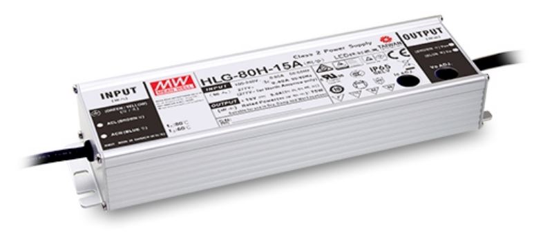
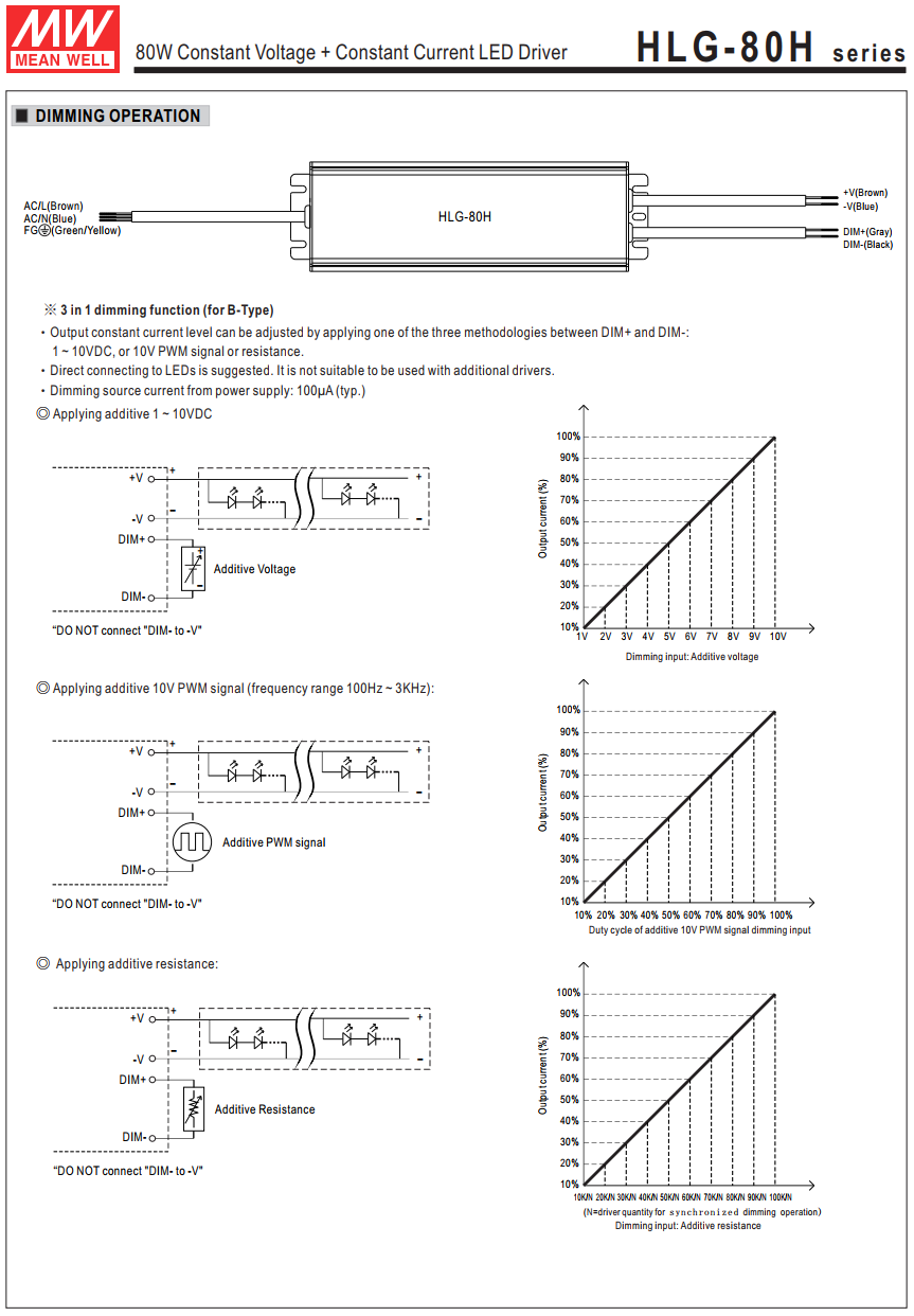
Many of the LED power supplies such as those by Mean Well, etc., offer three modes of control: output constant current level can be adjusted through the control input
by connecting a variable or fixed resistance to the control terminals,
using a 0 ~ 10 V DC control signal,
using a 10 V PWM signal between.
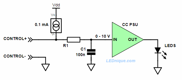
To do this the controller input is something similar to the circuit below.
Adjustable constant current PSU input circuit.
For DC voltage control we just apply the voltage, it gets to the controller with a slight lag depending on the R1/C1 delay and output power is set.
For PWM a pulse train would be used as shown in Figure 2. This time R1 and C1 filter the PWM to obtain the average DC value in the 0 to 10 V range. Output power is set as before.
PWM signal transitioning from high pulse width (75%) to low (25%) and back again. Note amplitude remains constant. This will result in a control input of 7.5 V and 2.5 V respectively giving 75% and 25% of rated current.
To sense a resistance connected to the input the PSU supplies a small current to the input terminals as shown by the constant current source. On the units I am familiar with 100 kΩ gives full brightness so that means the voltage drop across the 100 kΩ is 10 V and I = V/R = 10/100k = 0.1 mA.
This theory is supported by the fact that if you use one pot to control multiple power-supplies that the required pot value is 100/n where n is the number of power-supplies. This makes sense as each PSU will drive 0.1 mA into the pot. So for five lamps in parallel on the one pot R = V/I = 10/0.5m = 2 kΩ.
Finally, if nothing is connected to the control input the 0.1 mA will charge C1 to 10 V and give 100% brightness.
It’s simple and flexible and rather ingenious.
Link: Mean Well HLG-80H series. Note that these PSUs use a 1 – 10 V control signal rather than 0 – 10 V as discussed above. This will make little practical difference.
Datasheet extract
Mean Well HLG-80H dimmable PUS wiring and output vs control graphs.