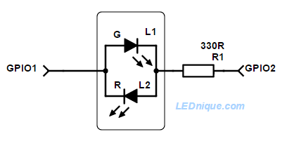
A bi-colour 2-pin LED can easily be switched to either colour or any blend in between with two GPIO pins.
If two GPIO1 pins are available controlling a 2-pin bi-colour back-to-back LED is simple.
How it works
To light L1, green, switch GPIO1 high and GPIO2 low. Current will flow from left to right.
To light L2, red, switch CPIO2 high and GPIO1 low. Current will flow from right to left.
To cross-fade or mix colours toggle between the two states above. A smooth blend can be obtained by varying the duty cycle.
To fade the LED set both of the outputs high or low for part of the time.
To switch off the LED set both of the outputs high or low. No current will flow and the LED will be dark.
The resistor can, of course, go on either side of the LED.
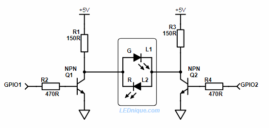
2 x GPIO controlling a higher voltage LED from a 3.3 V GPIO.
This circuit works in a similar manner to the simple one at the top of the page. If the GPIOs are both off then both sides of the LEDs are pulled high and the LEDs are off. To switch on the green Q2 is turned on and R1 sets the current. To switch on the red Q1 is turned on. To blend the colour the GPIOs are toggled alternately.
Note that turning both GPIOs on will turn off the LEDs but waste power through R1 and R2 (but without damage).
The schematic shows a 5 V supply but this could be used for 12 or 24 V LEDs provided the transistor is suitably rated for both voltage and current.
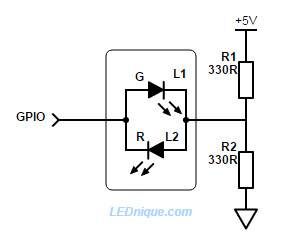
Driving a bi-colour, 2-pin LED with one pin is possible!
A single GPIO pin driving a bi-colour, 2-pin LED.
When GPIO1 pins are in short supply a bi-colour 2-pin LED may seem like a good idea.
It can be done, but is not that efficient.
How it works
When GPIO is low R1 provides current to L2 and the indicator glows red.
When GPIO is high current flows through L1 and R2 to ground and the indicator glows green.
By alternating the GPIO high-low fast enough both LEDs can be illuminated giving an orange colour (since they’re both in the same package). By varying the ‘on’ pulse width a smooth cross-fade can be given from red to green.
If the GPIO is tri-stated (disconnected) the LED will be dark.
Note that this circuit is not very efficient. R1 and R2 pass current to ground always and when the red LED is on R2 is stealing power from it and when the green LED is on R1 is stealing power from it. It may take some experimentation to get this to work.
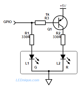
Figure 1. A single GPIO pin alternating the two LEDs of a common cathode dual LED.
When GPIO1 pins are in short supply a dual red-green common-cathode LED can still be used with the addition of a PNP transistor and base resistor.
How it works
When the GPIO pin is high L1, green, is turned on. There is no bias current for Q1 so it remains off and L2, red, is dark.
When the GPIO pin is low L1 is dark but current flows from the base of Q1 via R3 to the GPIO pin. This turns on Q1 and L2, red, will illuminate.
By alternating the GPIO high-low fast enough both LEDs can be illuminated giving an orange colour (since they’re both in the same package). By varying the ‘on’ pulse width a smooth cross-fade can be given from red to green.
If the GPIO is tri-stated (disconnected) there may be enough leakage current from the base via R3, R1 and L1 to turn Q1 on slightly and illuminate L2, red.
Inverter version
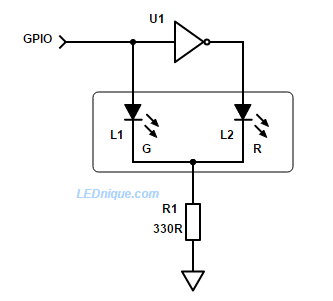
Figure 2. Using an inverter to alternate between two LEDs using one GPIO.
If there is a spare inverter on the board we can reduce component count as shown.
How it works
When the GPIO is high L1, green, is lit. U1 output is low and L2 is dark.
When the GPIO is low L1, green, is dark. U1 output is high and L2, red, is lit.
Note that this circuit shares a common resistor, R1, in the cathode. When L1 is on the cathode will rise to V+ – 2 V, approx., (the supply voltage minus the \(V_F\) of the LED) and the other LED will be reverse biased by that voltage. For supply voltages above 5 V this may cause reverse breakdown of the LED and so the arrangement below is better in that case.
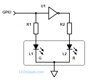
Inverter version for higher voltages
Figure 3. With an additional resistor there is no danger of reverse biasing the LED.
How it works
Operation is the same as Figure 2 but with the cathode firmly connected to ground neither LED is ever reverse biased.