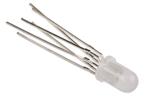
Most LEDs are simple single device with two leads but packages with two or more LEDs are common and there are various LED pinouts in use.
Simple LED test circuit

Most LEDs will light at less than 5 V and can tolerate 5 V reverse voltage. A 5 V supply is available from a USB supply or, for example, an Arduino. You can use a higher voltage such as a 9 V battery and double the value of R1 but you might damage sensitive devices on reverse voltage.
See Testing unknown LEDs for more on this topic.
Note that LEDs usually have no two pins the same length. This is for two reasons:
- It helps identify the pins.
- It helps during assembly as pins can be inserted one at a time from longest to shortest without having to align all the pins simultaneously.
2-pin
The most common type of LED is the 2-pin, 5 mm, round lens type. Generally these are a single LED. Polarity is indicated by the long lead (+ / anode) or the flat on one side of the base (- / cathode).


Be aware that bi-colour LEDs are also sold in this package. Some are dual-colour so that reversing the current through them changes the colour. Others may have both LEDs the same colour and this can be useful in AC applications as it can conduct on both cycles of the mains and eliminates the need for a rectifier.
The bi-colour LED’s datasheet will specify which way round to connect to ensure the correct colour.
3-pin

The three-pin LED is usually a pair of LEDs of different colours sharing a common anode or common cathode. Either LED can be turned on independently or blended to create a combination.

4-pin

The 4-pin package is most commonly seen on RGB (red-greeen-blue) LEDs. Common cathode and common anode versions are available.

6-pin


When the number of pins reaches six all sorts of strange variations are possible. One sensible one is to bring out each LED anode and cathode on individual pins. This allows a single part to be used for common anode, common cathode and series LED configurations.
A slightly strange 6-pin, RB-GB, LED, has two separate 3-pin LEDs in one package.


