
1 GPIO, 2 LEDs

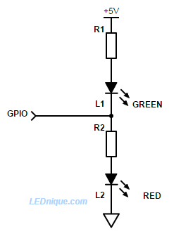
A single GPIO1 pin can be used to light two LEDs.
How it works
- When the output is switched low current will flow from the positive supply via R1 and the L1, green, to the output pin. L1 will illuminate. L2, red, will be shorted out and will be dark.
- When the output is switched high current will flow from the pin through R2 and L2. The red LED will illuminate and the green will be dark.
- If the output is tri-stated (wired as an input or disconnected by program control) a current will flow through R1, L1, R2, L2 and both LEDs will glow dimly. On a 3.3 V device the voltage wouldn’t be high enough to illuminate both LEDs significantly so they would appear dark.
- By rapidly (> 25 Hz should be enough) alternately switching the output high and low while varying the duty-cycle the red and green can be blended to give any colour in between the two.
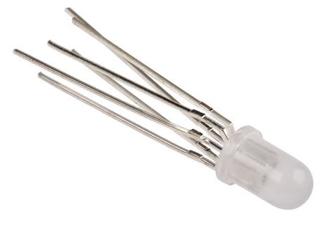
Note that to incorporate the 6-pin LED of Figure 3 into the circuit of Figure 1 you would control two of the three LEDs but leave the third unconnected, driven permanently or from another GPIO.
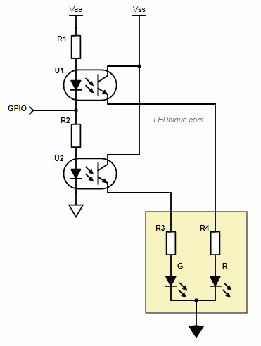
The same trick can be used to switch isolated or non-isolated loads using opto-isolators. When the GPIO is high U2 will be turned on. When low, U1 will be turned on.
1 switch, 2 LEDs
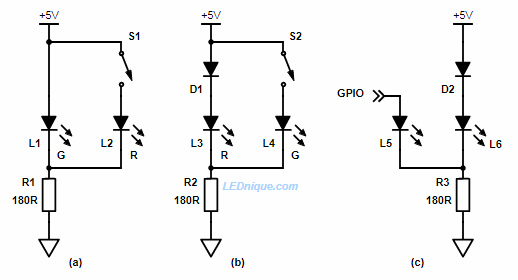
In (a) above the green LED is normally lit. There will be about 2.1 V across the LED.
When S1 is closed the red LED will turn on but since it’s forward voltage drop is only about 1.75 V the current in the green will drop very low. A look at the load-line graph shows us why.
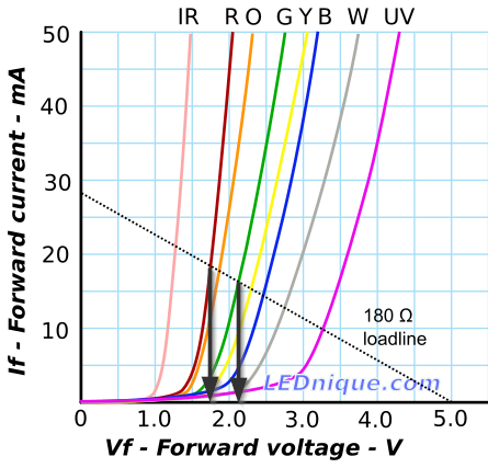
When the red LED is in circuit the LED voltage drops to 1.75 V or so. At this voltage the green only passes a couple of mA and will be off or dim.
If you want the circuit to operate the other way around as in Figure 5b then you need to induce further voltage drop. D1 achieves this. Now the combination of D1 and L3 will drop about 0.7 + 1.75 = 2.45 V. When the green is switched on there won’t be enough forward voltage to light the red (brightly).
The diode can be added to Figure 1a to reduce current further if the reduced current proves to be too bright.
The circuit will work with a GPIO output as shown in Figure 5c. In this case the additional diode, D2, will almost certainly be required as the GPIO will not reach +5 V when under load.
- Read about other GPIO tricks.
- Read about the Loadline resistance graphic tool.
- See Ohm’s law to work out the resistor values.


