

The LM317 adjustable voltage regulator can be used to make a simple constant-current power supply. The device is over forty years old but is still very popular with beginners due to it’s low cost, availability and thousands of practical applications. LM317 datasheet.
Constant current
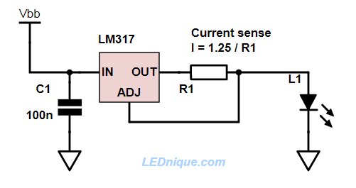
The LM317 regulates by adjusting it’s output until it is 1.25 V higher than the voltage on the adjust pin. For a constant current supply we just need to add in a series resistor to drop 1.25 V at the required current.
The LM317 can handle currents up to 1.5 A but be careful to so some power dissipation calculations and heatsink adequately if the power goes over a watt or two. (See ‘Temperature rise’ below.)
Voltage drop and headroom
For the LM317 to regulate properly it must have adequate supply voltage to allow for the sum of the voltage drops in the circuit. These are:
- The minimum voltage drop across the regulator itself. This is quoted in the datasheet as the difference between input and output voltage, \( V_I – V_O \) = 3 V.
- The voltage drop across R1. This is always 1.25 V.
- The voltage drop across the load. For LEDs it will be \( V_f \times n \) where \( V_f \) is the forward voltage drop of each LED and \( n \) is the number of series LEDs.
Explaining the ‘headroom’ voltage
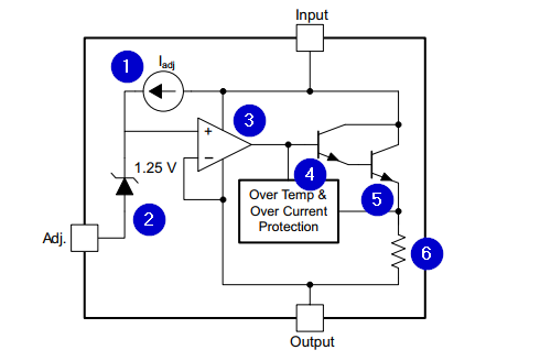
- The \( I_{adj} \) reference current generator feeds 50 to 100 µA through the 1.25 V voltage reference.
- The built-in Zener means that the op-amp inputs won’t equalise until the voltage on the output is 1.25 V above the adjust pin.
- If the output voltage is low then the op-amp inverting input voltage will fall below that of the non-inverting input and the op-amp output will rise.
- As (3) rises the Darlington transistor will turn on …
- … turning on the second transistor. The Darlington arrangement will cause about 2 × 0.7 = 1.4 V of the voltage drop between the input and output due to the forward voltage of the two base-emitter junctions.
- Finally the internal current sense resistor will account for most of the remainder of the voltage drop. (The op-amp may require a little more than 4, 5 and 6.)
Calculation example
Calculate the value of R1 to supply 100 mA to 5 series-connected blue LEDs with \( V_f \) = 3.1 V. The circuit will be powered from a 24 V supply.
First the resistor: \(R = \frac {V_{REF}}{I} = \frac {1.25}{0.1} = 12.5 \ \Omega \).
Now check the required input voltage:
\( V_{IN\ min} = 3 + 1.25 + 3.1 \times 5 = 19.75 \ \mathrm V \) minimum. Our 24 V supply is above this so it is fine.
We need to do one more thing: calculate the power dissipated in the LM317. This will be the voltage across the LM317 times the current:
\( P = ( V_{IN} – V_{OUT}) I = (24 – 19.75) \times 0.1 = 4.25 \times 0.1 = 0.425 \ \mathrm{W} \)Temperature rise
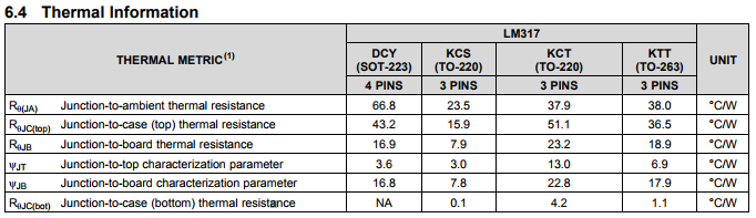
We’ll take a simple approach and use the LM317’s \( R_{\theta (JA)} \), the Junction to Ambient thermal resistance parameter (and abuse it as complained about in TI’s Application Report SPRA953C). Frot the KCT TO-220 package this is 37.9°C/W. This results in a temperature rise of \(\) 37.9 \times 0.425 = 16.1°C. Even with reasonably high ambient surroundings the junction temperature will come nowhere near its 125°C maximum.


