
Driving a bi-colour LED with one pin is possible!

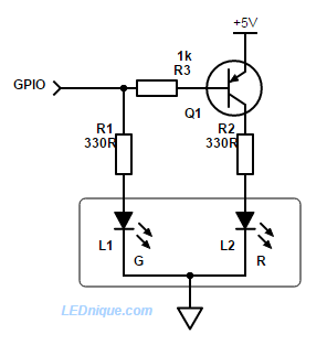
When GPIO1 pins are in short supply a dual red-green common-cathode LED can still be used with the addition of a PNP transistor and base resistor.
How it works
- When the GPIO pin is high L1, green, is turned on. There is no bias current for Q1 so it remains off and L2, red, is dark.
- When the GPIO pin is low L1 is dark but current flows from the base of Q1 via R3 to the GPIO pin. This turns on Q1 and L2, red, will illuminate.
- By alternating the GPIO high-low fast enough both LEDs can be illuminated giving an orange colour (since they’re both in the same package). By varying the ‘on’ pulse width a smooth cross-fade can be given from red to green.
- If the GPIO is tri-stated (disconnected) there may be enough leakage current from the base via R3, R1 and L1 to turn Q1 on slightly and illuminate L2, red.
Inverter version
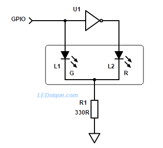
If there is a spare inverter on the board we can reduce component count as shown.
How it works
- When the GPIO is high L1, green, is lit. U1 output is low and L2 is dark.
- When the GPIO is low L1, green, is dark. U1 output is high and L2, red, is lit.
Note that this circuit shares a common resistor, R1, in the cathode. When L1 is on the cathode will rise to V+ – 2 V, approx., (the supply voltage minus the \(V_F\) of the LED) and the other LED will be reverse biased by that voltage. For supply voltages above 5 V this may cause reverse breakdown of the LED and so the arrangement below is better in that case.
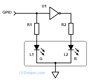
Inverter version for higher voltages
How it works
Operation is the same as Figure 2 but with the cathode firmly connected to ground neither LED is ever reverse biased.
See also 1 GPIO – 2 LEDs.


