LEDs are replacing incandescent light bulbs in many applications and over the next decade or so we are likely to see very few bulbs in new products. There will always be special cases where certain features of the light bulb make it the best choice – e.g., broad continuous spectrum or both light and heat are required.
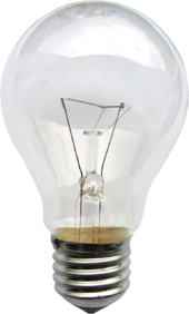
Incandescent light bulb
LEDs differ from light bulbs in many respects.
- Light bulbs are resistors designed to glow white-hot when connected to the rated voltage. They can heat up to 2,500°C.
- They behave like resistors. But like most metallic resistors the resistance increases with temperature. (This means that the temperature coefficient of resistance is positive – a PTC.)
- When cold the resistance is much lower than running temperature so the initial surge current can be 15 times that of the steady state current. For example, a 100-watt, 120-volt lamp has a resistance of 144 Ω when lit, but the cold resistance is much lower (about 9.5 Ω). This is why incandescent bulbs are prone to blow on switch-on. A weakened filament will burn
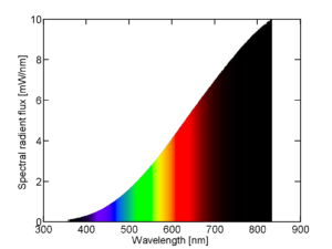
Spectral power distribution of a 25 W incandescent light bulb. out with the high inrush current.
- They can be run on DC or AC.
- Bulbs are tolerant of voltage variation of ±10% which is normal on mains supplies.
- Bulbs can be made to run directly on a wide range of voltages such as 3 V bicycle lamps to mains voltage lamps of several hundred volts.
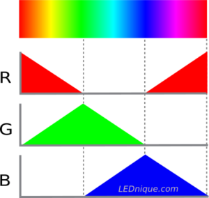
- Bulbs emit light over a broad spectrum from infra-red through the visible spectrum but heavily weighted to the red end. This is most noticeable in film photos which exhibited a characteristic tungsten red cast. The broad spectrum should not be confused with mixing specific colours or wavelengths to fool the eye into seeing white light.
- Bulbs are fragile.
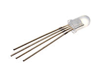
LEDs
LEDs are different in nearly every regard.
- LEDs drop in apparent resistance with rising voltage. This is due to the diode’s IV curve. See IV curves.
- LEDs have a slight negative temperature coefficient (NTC) value. This means that as they warm up they will pass more current and tend to heat further. If not managed this will lead to over-current failure. See LEDs in parallel – the problem.
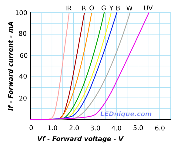
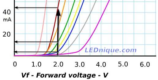
- LEDs are low voltage. Typical LED forward voltages are 1.2 V (infra-red) to 5 V (white).
- LEDs cannot handle negative voltages and require a DC supply. Most LEDs are rated for maximum 5 V reverse voltage.
- LEDs are sensitive to electro-static discharge (ESD). (Bulbs are not.)
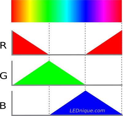
- LEDs’ colour is a function of the semiconductor material and are available in colours from infra-red to ultra-violet. See RGB LED.
- LEDs can detect light with a small output current like photodiodes.
- LEDs are single sided even with a transparent substrate.