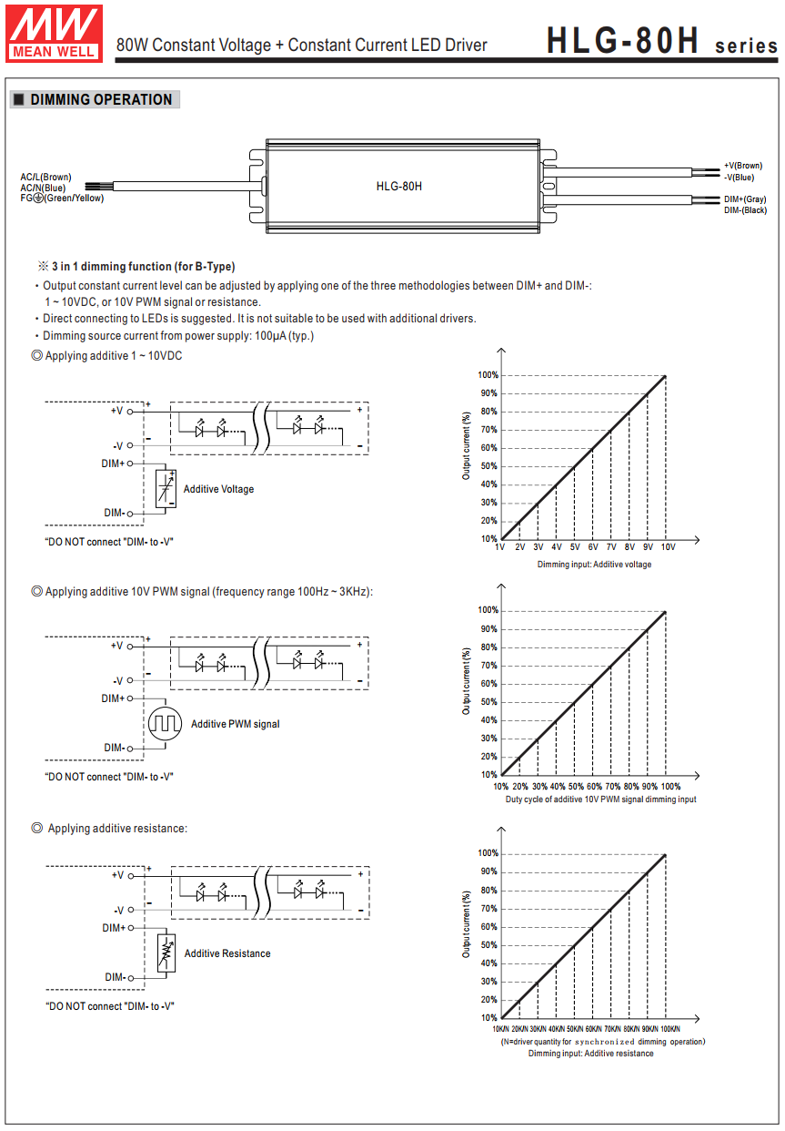
Many of the LED power supplies such as those by Mean Well, etc., offer three modes of control: output constant current level can be adjusted through the control input
- by connecting a variable or fixed resistance to the control terminals,
- using a 0 ~ 10 V DC control signal,
- using a 10 V PWM signal between.
To do this the controller input is something similar to the circuit below.
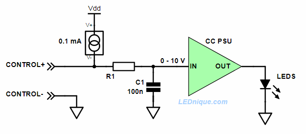
- For DC voltage control we just apply the voltage, it gets to the controller with a slight lag depending on the R1/C1 delay and output power is set.
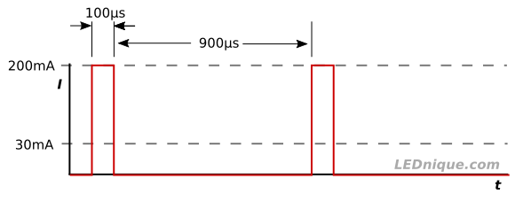
- For PWM a pulse train would be used as shown in Figure 2. This time R1 and C1 filter the PWM to obtain the average DC value in the 0 to 10 V range. Output power is set as before.

PWM signal transitioning from high pulse width (75%) to low (25%) and back again. Note amplitude remains constant. This will result in a control input of 7.5 V and 2.5 V respectively giving 75% and 25% of rated current. - To sense a resistance connected to the input the PSU supplies a small current to the input terminals as shown by the constant current source. On the units I am familiar with 100 kΩ gives full brightness so that means the voltage drop across the 100 kΩ is 10 V and I = V/R = 10/100k = 0.1 mA.
This theory is supported by the fact that if you use one pot to control multiple power-supplies that the required pot value is 100/n where n is the number of power-supplies. This makes sense as each PSU will drive 0.1 mA into the pot. So for five lamps in parallel on the one pot R = V/I = 10/0.5m = 2 kΩ. - Finally, if nothing is connected to the control input the 0.1 mA will charge C1 to 10 V and give 100% brightness.
It’s simple and flexible and rather ingenious.
Link: Mean Well HLG-80H series. Note that these PSUs use a 1 – 10 V control signal rather than 0 – 10 V as discussed above. This will make little practical difference.
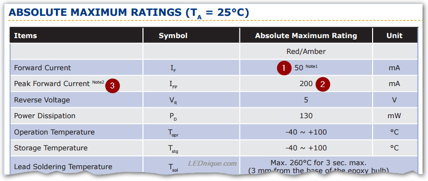
Datasheet extract