
“Ground” is a reference point in an electrical circuit. It is used as a reference point for voltage measurements. As a result a voltage may be above ground (positive) or below ground (negative). This is very like a surveyor taking a reference point in a certain location and referencing all other points to that datum.
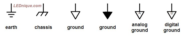
Earth
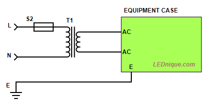
The most common reference is Earth itself. Power systems are usually “earthed” at some point to provide a reference for the system voltages. The earth symbol represents the parallel plates that were buried in the soil to ensure good conductivity. (The plates were connected by wire and early forms of the symbol show the vertical line connecting all the plates. The modern “cleaner” symbol omits the vertical.)
Chassis
The chassis symbol usually indicates connection to a metal frame such as that of a vehicle or metal case of a piece of equipment such as an amplifier or oscilloscope.
When used with the standard GND symbol below it will often appear only once to indicate the point in the circuit where the chassis connection is made.
Ground or GND
The ground symbols indicate the generic reference point. Even if there is no earth or chassis connection it is common to refer to one point or voltage in the circuit as “ground”. In equipment where electrical isolation is provided between sections of the circuit two or more ground symbols may be required to indicate which ground the components are connected to.
Analog and digital ground

In circuits with mixed analog and digital circuits it can be very important to prevent digital switching currents interfering with the analog signals. In audio circuits, for example, failure to do this would result in audible noise on the output. The solution is to provide analog and digital grounds and only connect them together at one point so that currents in the digital ground can’t cause any voltage fluctuations in the audio ground.
Voltage measurement examples

When taking voltage measurements it is normal practice to connect the common, black, lead to circuit common and probe other points in the circuit with the V, red, lead. The results for various configurations of a 9 V battery are shown above. The meter will display a positive or negative value depending on the point’s potential relative to the chosen ground reference.
Note that in these examples circuits that there is no connection to earth or mains ground. That doesn’t matter in most cases as we are only interested in the relative voltages within the circuit.
Virtual ground
In many analog circuits it is useful to have a “virtual ground” which is typically the mid-point of the single-ended supply. These are popular on guitar effects units, for example, where music signals have to be processed but the supply is constrained to a single 9 V battery.
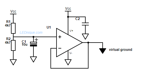
How it works:
- R1 and 2 provide a VCC/2 reference.
- C1 stabilises the reference voltage and keeps it constant during fluctuations in VCC.
- U1 provides the virtual ground.
- C2 is the supply decoupling capacitor for the op-amp.
See also
- Opto-triacs, solid-state relays (SSR), zero-cross and how they work.
- Opto-isolators.